Getting Started with the IMX6SLEVK
Contents of this document
-
Out of the Box
-
Get Software
-
Build and Run
Sign in to save your progress. Don't have an account? Create one.
Purchase your i.MX 6SL Evalutaion Kit
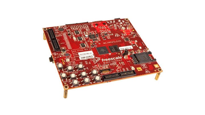
1. Out of the Box
This page will help guide you through learning about the NXP Linux® OS BSP and i.MX6SL EVK.
Evaluation Kit Contains:
- MCIMX6SLEVK
- Micro USB-B-2-USB-Type A male, V2.0 cable
- 100/240 V input, 5 V, 2.4 A output W/AC adaptor power supply
- Quick Start Guide
- Two SD cards: Programmed Android™


1.2 Insert the SD Card (SD3)
The kit comes with an SD card with a pre-built NXP Linux® BSP image. Without modifying the system, booting from the image will provide a default system with certain features for building other applications on top of Linux®.
To understand more about NXP Linux® BSP image, please continue reading the next section: BSP Introduction.
1.3 Connect USB Debug Cable
Connect the micro-B end of the supplied USB cable into Debug UART port J509. Connect the other end of the cable to a host computer.
Terminal window configuration: 115200 baud, 8 data bits, 1 stop bit, no parity.
Serial Communication Console setup- Linux®
On Linux® host machine, run the following command to determine the port number:
$ ls /dev/ttyUSB*
Use the following command to install serial communication program:
$ sudo apt-get install minicom$DYNHTML
Serial Communication Console setup -Windows
On Windows, to determine the port number of the i.MX board virtual COM port, open the device manager and look under the "Ports" group.
If needed, the serial-to-USB drivers can be found at FTDI Chip Drivers.
Not sure how to use a terminal application? Try one of these tutorials: Tera Term Tutorial, PuTTY Tutorial.
1.4 Connect HDMI (optional)
Connect an HDMI cable to the HDMI connector J8. Connect the other end to the HDMI cable to an HDMI capable monitor.
1.5 Connect User Interface Devices (optional)
Attach a keyboard and mouse to interact with the OS GUI displayed on the monitor. Attach a micro-USB hub to micro-USB jack J505 and connect the keyboard and mouse to the hub if more than one devices are used.
1.7 Connect Power Supply
Connect the 5 V power supply cable to the 5 V DC power jack P1.
When powered on, the processor starts executing code from on-chip ROM. With default Boot Switch setup, this code reads the fuses to find out which media to search for a bootable image. Then it will find the SD card and begin U-Boot execution automatically.
Information will be printed in the serial console. If you don't stop the U-boot process, it will boot the Linux® kernel.
1.8 Congratulations Your Linux® is booted
Once Linux® is booted, you can login with username root and no password.
To jump in U-Boot, press any key before the value of the U-Boot environment variable, "bootdelay", decreases and before it times out (default 3 seconds). If you stop the U-boot process, you can run the following command to boot Linux® again: U-Boot >boot
2. Get Software
Choose a Development Path:
i.MX Linux® Board Support Package
- Long-Term Support Kernel Release
- U-Boot
OR
i.MX Android™ Board Support Package
- Android™ Compatibility Test Suite (CTS) compatible Release
- Extended Multimedia Features
2.1 Overview
Before the Linux® OS kernel can boot on an i.MX board, the Linux® image needs to be copied to a boot device and the boot switches need to be set to boot that device.
To bring up the board and run Linux®, four elements are needed:
- Boot loader (U-Boot)
- Linux® kernel image (
zImage) - A device tree file (
.dtb) for the board being used - A root file system (
rootfs) for the particular Linux® image
2.2 Prepare a Linux® BSP Image
Pre-built Image
The release contains a pre-built SD card image that is built specifically for the i.MX 6Quad Sabre-SD board. The SD
card image is a file that is typically named <board name.sdcard> and is a specially constructed
disk image including partitions and all necessary files to boot the board, including all four components mentioned
above.</board>
The pre-built NXP Linux® Binary Demo Image provides a typical system and basic set of features for using and evaluating the processor. Without modifying the system, the users can evaluate hardware interfaces, test SoC features, and run user space applications.
Self-built Image
With the source code and documentation, the users also can customize the Linux® image built for your own device, i.e. add or remove system components.
The Yocto Project is the framework of choice with NXP professional support to build the images that are used for booting a Linux® kernel, although other methods can be used.
For more details, see NXP Yocto Project User's Guide.
2.3 Download Linux® BSP Image
There are various ways to download the Linux® BSP image for different boards, boot devices, and results desired.
For Getting-Started, we only list the few methods to transfer the BSP image to SD card.Experienced Linux® developer can explore other options.
The .sdcard image (either from a pre-built or self-built BSP image) is an SD card image that can be
flashed directly. This is the simplest way to load everything needed onto the card with one command.
When more flexibility is desired, an SD card can be loaded with the individual components (bootloader, kernel, dtb
file and rootfs file) one-by-one or the .sdcard image can be loaded and the individual parts can be
overwritten with the specific components.
Copying the full SD card image
An SD/MMC card reader is required to transfer the bootloader and kernel images to initialize the partition table and copy the root file system.
Linux® host:
The Linux® kernel running on the Linux® host assigns a device node to the SD/MMC card reader.
To identify the device node assigned to the SD/MMC card, carry out the following command in the host computer:
$ cat /proc/partitions
The instructions below will permanently delete existing content on the SD card and are dangerous to your PC if run incorrectly. If you have question or would like further details please consult the i.MX Linux® User's Guide.
Carry out the following command to copy the SD card image to the SD/MMC card. Change sdx below to match the one used by the SD card.
$ sudo dd if=<filename.sdcard> of=/dev/sd<x> bs=1M && sync </x></filename.sdcard>
where <filename.sdcard>filename.sdcard> is the correct board specific SD card
image</filename.sdcard>.
Make sure that the device node is correct for the SD/MMC card. Otherwise, it may damage your operating system or data on the hard disk of your computer.
To setup the partition manually, please read 4.3.3 in i.MX Linux® User's Guide.
To load individual component separately when the full SD card image is not used, please read 4.3.4-3.4.6 in i.MX Linux® User's Guide.
Using U-Boot
The Manufacturing Tool, named MfgTool, is a tool that runs on a Windows OS host and is used to download images to different devices on an i.MX board. The tar.gz file can be found with the pre-built Linux® BSP image.
Manufacturing Tool Tutorial - Linux
- Connect a USB cable from a computer to the USB OTG port on the board
- No dedicated boot DIP switches are reserved for serial download mode on i.MX 6 Quad/QuadPlus SABRE-SD board. One way is to set the boot mode to boot from SD slot SD3 but do not insert the SD card, and power on the board. After the message "HID Compliant device" is displayed, the board enters serial download mode. Then insert the SD card into SD slot SD3.See "4.5.11 Serial download mode for the Manufacturing Tool" in i.MX Linux® User Guide
- Power on the board
- Choose the correct
*.vbsfile according to the target device. The manufacturing tool automatically pulls the required files based on the device. The default profile of the Manufacturing Tool assumes that your file system is packed and compressed using the bzip2 algorithm. You can also modify the profile to support other formats - After the image downloading is done, set the boot switch to boot up the board. See next step in Section 2 in this Getting Started Tutorial or Section "How to boot the i.MX boards" in the document
For details, please refer to 4.2 Manufacutring Tool in i.MX Linux®User's Guide.
You can connect a USB cable from the debug UART port to the computer and open a serial communication program for for console output.

Using Manufacturing Tool
The U-Boot bootloader is able to download images over Ethernet to RAM and then writes to an SD card. For this operation. Network communications need to be configured.
For instructions about how to download U-Boot to an MMC/SD card that is not the one used to boot from, please refer to section 4.4.1.
Images can be downloaded to other boot media (memory storage device) using U-Boot.To use other memory device, please refer to sections under 4.4.1.
2.4 Boot Switch Setup
The boot modes of the i.MX boards are controlled by the boot configuration DIP switches on the board.
| S1_2 BOOT_MODE1 |
S1_1 BOOT_MODE0 |
|
|---|---|---|
| Boot from fuses | 0 | 0 |
| Serial DownloaderD | 0 | 1 |
| Internal Boot | 1 | 0 |
| Reserved | 1 | 1 |
| SW3_8 BT_CFG1_0 |
SW3_7 BT_CFG1_1 |
SW3_6 BT_CFG1_2 |
SW3_5 BT_CFG1_3 |
SW3_4 BT_CFG1_4 |
SW3_3 BT_CFG1_5 |
SW3_2 BT_CFG1_6 |
SW3_1 BT_CFG1_7 |
|
|---|---|---|---|---|---|---|---|---|
| SD1 | * | ** | * | * | * | 0 | 1 | 0 |
| SD2D | * | ** | * | * | * | 0 | 1 | 0 |
| SD3 | * | ** | * | * | * | 0 | 1 | 0 |
| SD4 | * | ** | * | * | * | 0 | 1 | 0 |
| EMMC | X | X | * | * | * | 1 | 1 | 0 |
| SPI NOR | X | X | X | X | 1 | 1 | 0 | 0 |
| SW4_8 BT_CFG2_0 |
SW4_7 BT_CFG2_1 |
SW4_6 BT_CFG2_2 |
SW4_5 BT_CFG2_3 |
SW4_4 BT_CFG2_4 |
SW4_3 BT_CFG2_5 |
SW4_2 BT_CFG2_6 |
SW4_1 BT_CFG2_7 |
|
|---|---|---|---|---|---|---|---|---|
| SD1 | * | X | X | 0 | 0 | 1 | * | * |
| SD2D | * | X | X | 1 | 0 | 1 | * | * |
| SD3 | * | X | X | 0 | 1 | 1 | * | * |
| SD4 | * | X | X | 1 | 1 | 1 | * | * |
| EMMC | * | * | * | 1 | 0 | 0 | 1 | 1 |
| SPI NOR | X | X | X | X | X | X | X | X |
| SW5_8 BT_CFG4_0 |
SW5_7 BT_CFG4_1 |
SW5_6 BT_CFG4_2 |
SW5_5 BT_CFG4_3 |
SW5_4 BT_CFG4_4 |
SW5_3 BT_CFG4_5 |
SW5_2 BT_CFG4_6 |
SW5_1 BT_CFG4_7 |
|
|---|---|---|---|---|---|---|---|---|
| SD1 | X | X | X | X | X | X | X | X |
| SD2D | X | X | X | X | X | X | X | X |
| SD3 | X | X | X | X | X | X | X | X |
| SD4 | X | X | X | X | X | X | X | X |
| EMMC | X | X | X | X | X | X | X | X |
| SPI NOR | 0 | 0 | 0 | 1 | 0 | 0 | X | X |
X: None specified
D: Default configuration
*: Switch needs to be configured for high or low depending on the application needs. Please check reference manual for boot configuration options.
**: 1 = power cycle on power-up via SDa_RST_B (SD3_RST). 0 = no power cycle
For boot switch setup to boot from other device (SD3 and SATA), please refer to 4.5 in i.MX Linux® User Guide
3. Build and Run
3.1 Key Features Demo in Linux®
With Linux® running on the i.MX platform, you can evaluate special features that i.MX SoCs provide:
Power Management
There are three main power management techniques on i.MX boards:
- Suspend and resume commands
- CPU frequency scaling
- Bus frequency scaling
After Linux® setup, for more details about developing applications in user space. Please see i.MX6 Linux® Reference Manual.
Multimedia
After Linux® setup, for more details about developing applications in user space. Please see i.MX6 Linux® Reference Manual.
Graphics
- For more details go to Chapter 8 of I.MX Linux® User's Guide
-
For more details of graphic APIs and driver support, see i.MX6 Graphics User's Guide
- The purpose of this document is to provide information on graphic APIs and driver support. Each chapter describes a specific set of APIs or driver integration as well as specific hardware acceleration customization. The target audiences for this document are developers writing graphics applications or video drivers
- i.MX G2D API
- i.MX 6 EGL and OGL Extension Support
- For more details of Video Processing Unit, see i.MX VPU programming interface Linux® Reference Manual
Security
- For more details go to Chapter 9 of i.MX Linux® User's Guide
- For details of secure system upgrade, read i.MX Linux® High Assurance Boot User's Guide
Connectivity
- Bluetooth support works best with a USB dongle with either BlueZ4 or BlueZ5
- Broadcom Wi-Fi and Bluetooth wireless technology support require the Broadcom firmware package download from i.MX Software and Development Tools. The Broadcom device drivers are integrated into the kernel but to function require the firmware package download and integration
- For more details go to Chapter 10 of i.MX Linux® User's Guide
3.2 Application development
After Linux® setup, for more details about developing applications in user space. Please see i.MX6 Linux® Reference Manual.
3.3 Yocto Project
NXP Yocto Project User's Guide covers how to set up the Linux® host machine, how to run and configure a Yocto Project, generate an image, and generate a rootfs.
For more details, see NXP Yocto Project User's Guide.
3.4 Extended Features in Android™
Wi-Fi Display Sink API
The i.MX Android™ Wi-Fi Display Sink APIs allows a device to act as Wi-Fi Display Sink to render the audio and video contents from Wi-Fi Display Source in real time.
Using the i.MX Android™ Wi-Fi Display Sink APIs, an Android™ application can perform the following:
- Scan for other Wi-Fi Display Source devices
- Get self peer name and MAC address
- Set the device name which is displayed in other Wi-Fi Display devices
- Set the display surface to render the RTSP streaming from the Wi-Fi Display Source Device
- Start or stop the RTSP streaming between Wi-Fi Display Source and Sink
- Disconnect Wi-Fi display connection from P2P layer
- Send the input event to the Wi-Fi Display Source device, which known as UIBC
The HDCP2.X (High-bandwidth Digital Content Protection) function based on the Android™ Extended Wi-Fi Display Sink Release package is designed to create a secure connection between a source and a display by enabling:
- The High Assurance Boot (HAB) for an Android™ image
- Generation and provision keyblob for HDCP2.X key
Extended Codec
The features described in the release notes are supported by NXP implemented media framework OMXPlayer. They are only available after applied android_L5.1.1_2.0.0-ga_omxplayer_source.tar.gz software package.
Only codecs that have no license restriction are included in OMXPlayer package.
Check Video/Audio decoder/encoder in i.MX Android Extended Codec Release Notes
To install the OMXPlayer package, perform the following steps:
- Copy the OMXPlayer package to the Android™ root directory
- Go to the Android™ root directory and decompress the OMXPlayer package
This step generates the device/fsl-codec, external/fsl_imx_omx, lean_obj_before_building.sh, and switch_build_to.sh.
12345$ source build/envsetup.sh
$ lunch <target build platform> # e.g., sabresd_6dq-user</target>
$./switch_build_to.sh full
$./clean_obj_before_building.sh
$make3.5 Further Resources
LCD/HDMI SD CARD for Booting Android
The default boot mode configures the system to display the UI on the MCIMX28LCD (sold separately). To change the default configuration and enable the MCIMXHDMICARD daughte rcard (sold separately), hit any key to stop u-boot from proceeding. Once prompt is visible, the u-boot can be configured as follows:
For LCD boot up, type the following commands (as one line):
setenv bootargs console=ttymxc0,115200 init=/initandroidboot.console=ttymxc0panel=lcdsaveenvreset
For HDMI boot up, type the following commands (as one line):
setenv bootargs console=ttymxc0,115200 init=/initandroidboot.console=ttymxc0panel=hdmisaveenvreset
EPDC SD CARD for Booting Android
The default settings should be used and no change is needed.
Tera Term Tutorial
Tera Term Tutorial
Tera Term is a very popular open source terminal emulation application. This program can be used to display information sent from your NXP development platform's virtual serial port.
- Download Tera Term from SourceForge. After the download, run the installer and then return to this webpage to continue
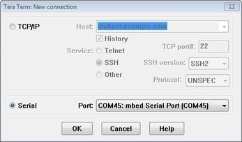
- Launch Tera Term. The first time it launches, it will show you the following dialog. Select the serial option. Assuming your board is plugged in, there should be a COM port automatically populated in the list
- Configure the serial port settings (using the COM port number identified earlier) to 115200 baud rate, 8 data bits, no parity and 1 stop bit. To do this, go to Setup → Serial Port and change the settings
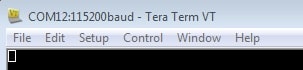
- Verify that the connection is open. If connected, Tera Term will show something like below in it's title bar
- You're ready to go
PuTTY Tutorial
PuTTY Tutorial
PuTTY is a popular terminal emulation application. This program can be used to display information sent from your NXP development platform's virtual serial port.
- Download PuTTY using the button below. After the download, run the installer and then return to this webpage to continue
- Launch PuTTY by either double clicking on the
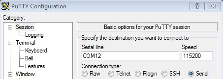
*.exefile you downloaded or from the Start menu, depending on the type of download you selected - Configure In the window that launches, select the Serial radio button and enter the COM port number that you determined earlier. Also enter the baud rate, in this case
115200 - Click Open to open the serial connection. Assuming the board is connected and you entered the correct COM port, the terminal window will open. If the configuration is not correct, PuTTY will alert you
- You're ready to go
On this page
- 1.1
Get Familiar with the Board
- 1.2
Insert the SD Card (SD3)
- 1.3
Connect USB Debug Cable
- 1.4
Connect HDMI (optional)
- 1.5
Connect User Interface Devices (optional)
- 1.6
Connect Ethernet Cable (optional)
- 1.7
Connect Power Supply
- 1.8
Congratulations Your Linux® is booted