
i.MX 6Solo Processors – Single-Core, Multimedia, 3D Graphics, Arm® Cortex®-A9 Core
The MMPF0100 is the first of the PF series of our PMICs, featuring:
The MMPF0100 is suited to all i.MX 6 processors: i.MX 6SoloX, i.MX 6SoloLite, i.MX 6Solo, i.MX 6DualLite, i.MX 6Dual, i.MX 6Quad, i.MX 6DualPlus and i.MX 6QuadPlus. It is built into multiple reference designs in the i.MX 6 family to provide a platform-level solution from that enables faster time to market.

i.MX 6QuadPlus Processor - Quad-Core, High-Performance, Advanced 3D Graphics, HD Video, Advanced Multimedia, Arm® Cortex®-A9 Core

i.MX 6DualLite Processors – Dual-Core, 3D Graphics, HD Video, Arm® Cortex®-A9 Core

i.MX 6DualPlus Processor - Dual-Core, High-Performance, Advanced 3D Graphics, HD Video, Advanced Multimedia, Arm® Cortex®-A9 Core

i.MX 6Quad Processors - High-Performance, 3D Graphics, HD Video, Arm® Cortex®-A9 Core
|
|
|
|
|
|
|
|---|---|---|---|---|---|
|
|
|
|
|
|
|
|
|
|
|
|
|
|
|
|
|
|
|
|
|
|
|
|
|
|
|
|
|
|
|
|
|
|
|
|
|
|
|
|
|
|
|
|
|
|
|
|
|
|
|
|
|
|
|
|
|
|
|
|
|
|
|
|
|
|
|
|
|
|
Quick reference to our documentation types.
1-5 of 17 documents
Please wait while your secure files are loading.
Receive the full breakdown. See the product footprint and more in the eCad file.

Receive the full breakdown. See the product footprint and more in the eCad file.
4 hardware offerings


Additional hardware available. View our featured partner solutions.
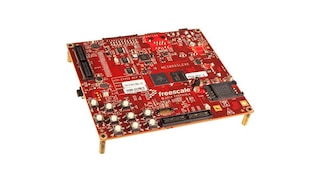
5 hardware offerings
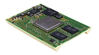
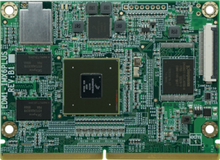

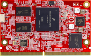
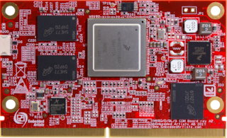
To find additional partner offerings that support this product, visit our Partner Marketplace.
4 engineering services


There are no results for this selection.
To find additional partner offerings that support this product, visit our Partner Marketplace.
1 trainings