- Analog Toolbox
- Getting Started with the PCAL9722HN-ARD Evaluation Board
Getting Started with the PCAL9722HN-ARD Evaluation Board
Contents of this document
-
Out of the Box
-
Get Hardware
-
Install Software
-
Configure Hardware
Sign in to save your progress. Don't have an account? Create one.
Purchase your PCAL9722HN-ARD
1. Out of the Box
The NXP analog product development boards provide an easy-to-use platform for evaluating NXP products. The boards support a range of analog, mixed-signal and power solutions. They incorporate monolithic integrated circuits and system-in-package devices that use proven high-volume technology. NXP products offer longer battery life, a smaller form factor, reduced component counts, lower cost and improved performance in powering state-of-the-art systems.
This page will guide you through the process of setting up and using the PCAL9722HN-ARD evaluation board.
2. Get Hardware
2.1 Board Features
- A complete evaluation platform for the PCAL9722HN, ultra low-voltage translating 22-bit SPI I/O expander with Agile I/O features, interrupt output and reset
- Easy to use GUI based software demonstrates the capabilities of the PCAL9722HN
- On-board LEDs, 7 segment display and key switches for PCAL9722HN general purpose I/O evaluation
- Convenient test points for easy scope measurements and signal access
- USB interface to the host PC
- Power supply from USB port or external power supply can be used to power PCAL9722HN-ARD evaluation board
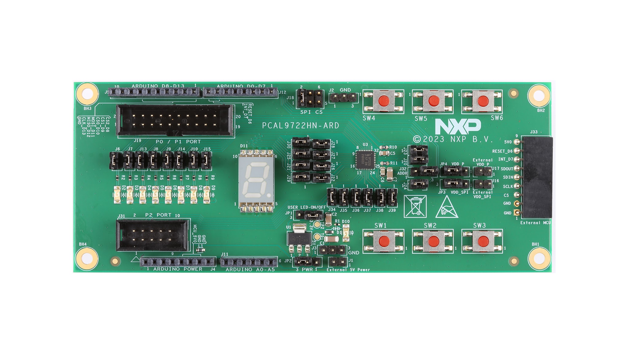
2.2 Board Description
The PCAL9722HN evaluation board features a 22-bit general purpose I/O expander that provides remote I/O expansion for most microcontroller families via the SPI interface. The board can be connected in parallel with other SPI-bus demo boards to create an evaluation system.
The IC communicates to the host via the industry standard SPI-bus port. The evaluation software runs under Microsoft Windows 7, 8 and 10 PC platform.
2.3 Board Components
PCAL9722HN-ARD evaluation board is connected to the
LPC55S69-EVK MCU board using
four connectors (J4/J5/J11/J12
on PCAL9722HN-ARD board and P16/P17/P19/P18 on LPC55S69-EVK board) for SPI-bus
and power supply.
The LPC55S69-EVK MCU board communicates with PCAL9722HN demo GUI through PC USB port and uses SPI to communicate to PCAL9722HN.
3. Install Software
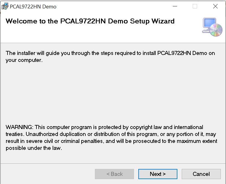
3.1 Install Software
Installing software is necessary to work with this evaluation board.
- Double click on “setup.exe” to install PCAL9722HN-ARD demo GUI
- Click “Next” button three times to complete installation
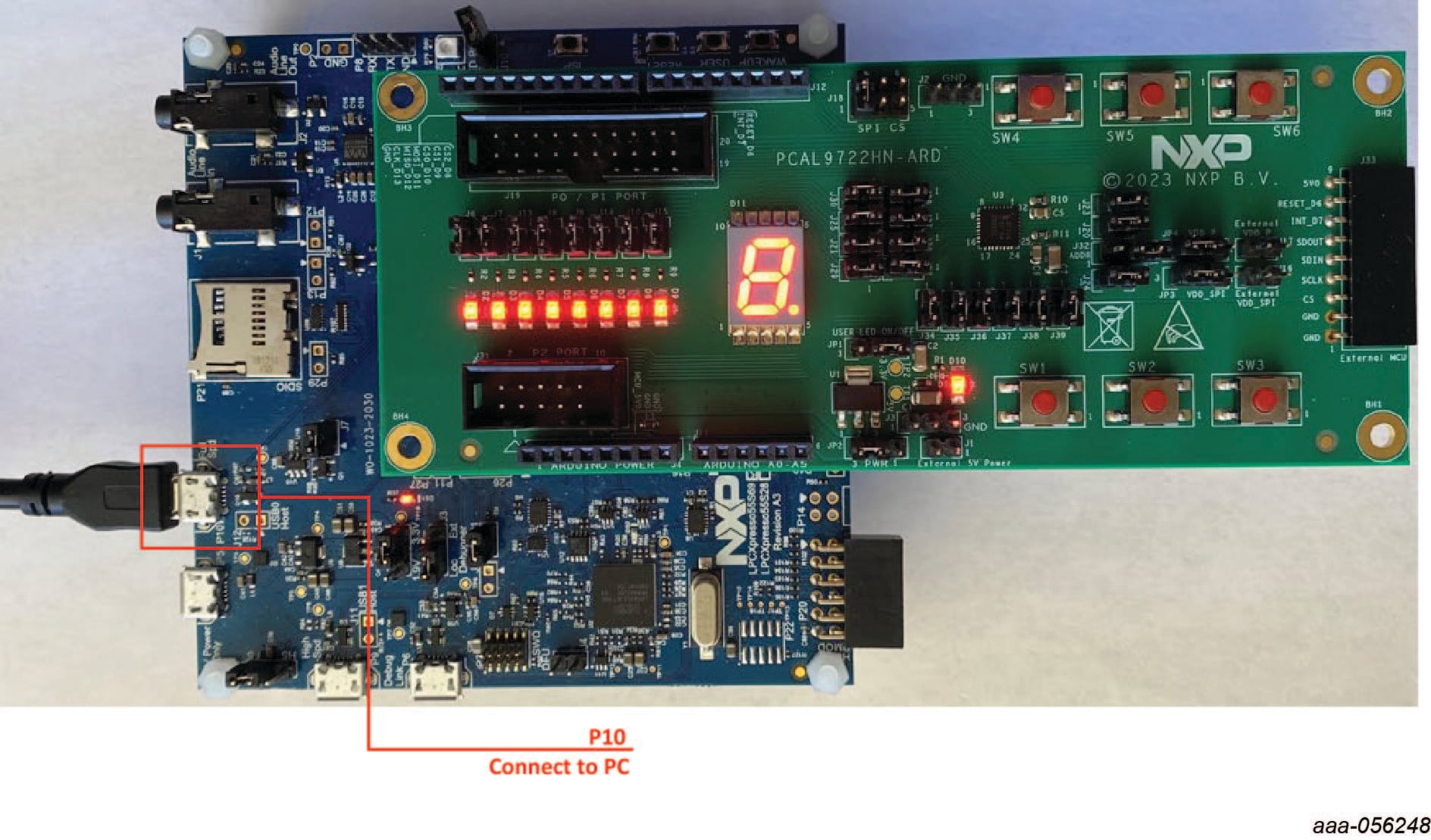
4. Configure Hardware
Figure 3 presents a typical hardware configuration.
Use P10 (USB micro-B connector) on LPC55S69-EVK for power supply and GUI communication port.
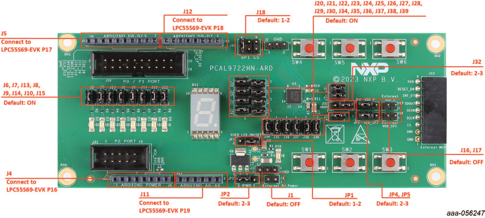
4.1 Hardware Description
J4/J5/J11/J12are connected to the LPC55S69-EVK MCU board for PCAL9722HN-ARD power supply and SPI-bus interfaceJP1selects user LED on/offJP2selects internal or external +5 V power supplyJP3selects internal or external VDD_SPI power supplyJP4selects internal or external VDD_P power supply
| Device | Description | Location |
|---|---|---|
| PCAL9722HN | I3C, SPI-bus, 0.5 °C accuracy, digital temperature sensor | U3 |
| 7 segment display | Displaying number | D11 |
| NCP117ST33T3G | 5 V to 3.3 V LDO | U1 |
| Red LED | Power supply on LED | D10 |
| Jumper | Default Setting | Comment |
|---|---|---|
J4, J5, J11, J12 |
- | Arduino connector |
J1 |
- | External 5 V power supply pins |
J2, J3 |
- | Ground test pins |
J6, J7, J13, J8, J9, J14, J10, J15 |
On | User LED current measurement pins |
J16 |
- | External VDD_SPI power supply pins |
J17 |
- | External VDD_P power supply pins |
J18 |
1-2 | SPI CS 0-2 select pins |
J19 |
- | Port 0 and 1 test pins |
J20 |
1-2 | SCK test pin |
J23 |
1-2 | SDIN test pin |
J24 |
1-2 | SDOUT test pin |
J21, J22, J25, J26, J27, J28, J29, J30 |
1-2 | 7 segment display test pins |
J31 |
- | Port 2 test pins |
J32 |
2-3 | ADDR select pin |
J33 |
- | External MCU connector |
J34, J35, J36, J37, J38, J39 |
1-2 | Key switch test pins |
JP1 |
1-2 | User LED on/off select pin |
JP2 |
2-3 | Internal or external +5 V power supply select pin |
JP3 |
2-3 | Internal or external VDD_SPI power supply select pin |
JP4 |
2-3 | Internal or external VDD_P power supply select pin |
Design Resources
Additional References
In addition to our PCAL9722: Low-Voltage Translating 22-Bit SPI I/O Expander page, you may also want to visit:
Application pages:
Other related products: