Getting Started with the S32K148-Q176 Evaluation Board
Contents of this document
-
Out of the Box
-
Get Software
-
Plug It In
-
Build, Load
Sign in to save your progress. Don't have an account? Create one.

Purchase your S32K148-Q176 Evaluation Board for Automotive General Purpose
1. Out of the Box


1.4 Understanding the USB/OpenSDA
OpenSDA is a serial and debug adapter that is built into several NXP® evaluation boards. It provides a bridge between your computer (or other USB host) and the embedded target processor, which can be used for debugging, flash programming and serial communication, all over a simple USB cable.
The OpenSDA hardware consists of a circuit featuring a Kinetis® K2x microcontroller with an integrated USB controller. On the software side, it implements a mass storage device bootloader, which offers a quick and easy way to load OpenSDA applications such as flash programmers, run-control debug interfaces, serial to USB converters and more.
| Jumper | Setting | Description |
|---|---|---|
J22 |
1-2 | RESET switch is routed RST MCU |
Note:
for RevA ONLY:
R537must be removed when the S32K148 EVB is powered only via USB/OPEN SDA- In order to enable SPI communication with the SBC
UJA1132,R177andR154must be removed to swap signals
PTA29/FTM5_CH4/LPUART2_TX/LPSPI1_SIN_LS and PTA27/FTM5_CH2/LPSPI1_SOUT/LPUART0_TX_LS by external wires


1.6 Understanding the HMI Mapping
| Component | S32K148 |
|---|---|
| Red LED | PTE21 |
| Blue LED | PTE23 |
| Green LED | PTE22 |
| Potentiometer | PTC28 |
| SW3 | PTC12 |
| SW4 | PTC13 |
| OpenSDA UART TX | PTC7 (LPUART1_TX) |
| OpenSDA UART RX | PTC6 (LPUART1_RX) |
| CAN TX | PTE5 (CAN0_TX) |
| CAN RX | PTE4 (CAN0_RX) |
| LIN1 TX | PTA3 (LPUART0_TX) |
| LIN1 RX | PTA2 (LPUART0_RX) |
| LIN2 TX | PTA9 (LPUART2_TX) |
| LIN2 RX | PTA8 (LPUART2_RX) |
| SBC_SCK | PTA28 (LPSPI1_SCK) |
| SBC_MISO | PTA29 (LPSPI1_SIN) |
| SBC_MOSI | PTA27 (LPSPI1_SOUT) |
| SBC_CS | PTA26 (LPSPI1_PCS0) |
2. Get Software
2.3 Get the Integrated Development Environment (IDE)
S32K144EVB performs better when using S32 Design Studio for Arm v1.3.
2.4 Get the Run-Time Debugging Tool
S32K144EVB evaluation board performs better when using the FreeMASTER tool for run-time debugging.
You can also download and install the FreeMASTER Communication Driver (source code already included in example project).
3. Plug It In
3.1 Set Up Jumpers
| Jumper | Setting | Description |
|---|---|---|
J7 |
1-2 | MCU VDD domain is connected to 3.3 V |
| 2-3 (Default) | MCU VDD domain is connected to 5 V | |
J8 |
1-2 (Default) | 5 V domain powered by 12 V power source |
| 2-3 | 5 V domain powered by USB micro connector | |
J12 |
1-2 (Default) | LIN leader option enabled for LIN1 |
J18 |
1-2 (Default) | VBAT(+12 V) is routed to the input of the 3V3 switching power supply |
| 2-3 | USB power (+5 V) is routed to the input of the 3V3 switching power supply | |
J19 |
1-2 (Default) | VDD is routed to VDD_MCU domain (remove in order to measure the MCU current) |
J21 |
1-2 (Default) | LIN leader option enabled for LIN2 |
J22 |
1-2 (Default) | Reset switch is routed to MCU reset line |
| 2-3 | Reset switch is routed to openSDA reset line |
3.2 Plug In the Power Supply
The S32K148-EVB evaluation board powers from a USB or external 12 V power supply.
USB power can be enabled with J8 (2-3) and J18 (2-3).
- Connect the USB cable to a PC using supplied USB cable.
- Connect other end of USB cable (microUSB) to micro-B port on S32K148EVB at
J24. - Allow the PC to automatically configure the USB drivers if needed.
Debug is done using OpenSDA through J24.
When powered using the USB, LED D10 should light green and LEDs DS2 and DS3 light orange.
4. Build, Load
4.1 Communicate with Debugger
- Launch the FreeMASTER application
-
Configure the communication port through OpenSDA with a 115200 b/s speed rate:
- To do this manually, go to Project → Options → Comm

- To do this automatically, go to Tools → Connection Wizard

- To do this manually, go to Project → Options → Comm

4.2 JumpStart Project Download
The FreeMASTER JumpStart project will be automatically downloaded from NXP Semiconductors once the FreeMASTER application detects the web address stored as a TSA active content in the flash.


4.4 Import and Debug the Project to IDE
-
Launch the S32 Design Studio for Arm® and select a default workspace or specify a new one. Then click OK
- Create a new project by selecting File → New → Project.
-
Create a project name. Select the project type in the executable or library folder. Then click Next.
You can select for project type from inside executable or library folder.
- Select Debugger Support and Library Support. Then click Finish


4.5 Set Up Debug Configuration
To debug your project with OpenSDA, your must first select OpenSDA.
- Select your project, and click Debug Configuration
- Under GDB PEMicro Interface Debugging, select the debug configuration. Then click the Debugger tab
- In Interface, select OpenSDA. If your board is plugged in, it should appear in Port. To finish, click Apply then Debug


FreeMASTER JumpStart Oscilloscope Feature


Create an Example from the SDK
Create an Example from the SDK
The S32 Design Studio IDE includes a software development kit (SDK) for quickly developing applications on S32K1xx devices.
- To get started, go to File → New → S32DS Project from Example
- Go to the S32K14x EAR SDK v0.8.6 Example Projects section and select the example you want to use. (in this case, the “hello_world” example is selected). Then click Finish
- The new project is created in the workspace. Click the generate code icon and then click the debug icon


The complete documentation of the SDK can be found in:
1C:\NXP\S32DS_ARM_v2018.R1\S32DS\S32SDK_S32K14x_EAR_0.8.6\doc\Start_here.htmlCheck Enabling Technologies: Hands-On Workshop: S32 SDK for S32K for more information about the use of the SDK.
Debug Basics
Debug Basics
Debug configuration is only required once. Subsequent starting of debugger does not require these steps.
There are three options for starting the debugger:
- If the debug configuration is still open, click Debug on the bottom right.
- Select Run → Debug
- Press (F11)

Recommended: Cpck the down arrow on the bug icon and select _debug.elf target

Step, Run, Suspend and Resume
-
Step Into (F5)

-
Step Over (F6)

-
Step Return (F7)

-
Run

-
Suspend

-
Resume (F8)


View and Alter Registers
To see CPU registers, click the Registers tab. To enter different values, click in the Value field.

"Click on a value to allow typing in a different value."
To see peripheral registers, click the EmbSys Registers tab.

View and Alter Memory
Click the plus icon + for Add Memory Monitor then select the base address to start at 40000000


Click the Memory tab.


Introduction to OpenSDA
Introduction to OpenSDA
OpenSDA is an open-standard serial and debug adapter. It bridges serial and debug communications between a USB host and an embedded target processor. OpenSDA software includes a flash-resident USB mass-storage device (MSD) bootloader and a collection of OpenSDA applications.
S32K148 EVB comes with the MSD Flash Programmer + Debug OpenSDA application preinstalled.
Follow these instructions to run the OpenSDA Bootloader and update or change the installed OpenSDA application.
| Enter OpenSDA Bootloader Mode | Load an OpenSDA Application |
|---|---|
A removable drive should now be visible in the host file system with a volume label of BOOTLOADER. You are now in OpenSDA bootloader mode. |
You are now running the latest version of the MSD flash programmer. Use this same procedure to load other OpenSDA applications. |
Note: Follow the “Load an OpenSDA Application” instructions to update the MSD Flash Programmer on your S32K148EVB to the latest version.
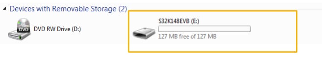
The MSD flash programmer + Debug is a composite USB application that provides a virtual serial port, a debug interface and an easy and convenient way to program applications into the S32K MCU. It emulates a FAT16 file system, appearing as a removable drive in the host file system with a volume label of S32K148EVB.
Raw binary and Motorola S-record files that are copied to the drive are programmed directly into the flash of the S32K148 and executed automatically. The virtual serial port enumerates as a standard serial port device that can be opened with standard serial terminal applications.
| Using the MSD Flash Programmer | Using the Virtual Serial Port |
|---|---|
The new application should now be running on the S32K148EVB. Starting with v1.03 of the MSD Flash Programmer, you can program repeatedly without the need to unplug and reattach the USB cable before reprogramming. Drag one of the |
|
Note:
Flash programming with the MSD Flash Programmer is currently only supported on Windows operating systems. However, the virtual serial port has been successfully tested on Windows, Linux and Mac operating systems.
Refer to the OpenSDA User's Guide for a description of a known Windows issue when disconnecting a virtual serial port while the COM port is in use.
Using Ethernet
The S32K148 evaluation board is the only member of its family able to use Ethernet and QuadSPI. However, these interfaces are mutually exclusive so only one of them can be used at a time. In order to use either Ethernet or QuadSPI, you must follow a specific resistor configuration. The default configuration of the board is to be used for Ethernet communication.
Using Ethernet on the S32K148EVB
Different from the rest of the devices on the S32K1xx family, the S32K148 has the ENET module, which offers the possibility to use Ethernet communication protocol. This enables this device for applications such as small Gateway (LIN-CAN-ETHERNET) or Audio Amplifier.
The software development kit (SDK) for the S32K1xx devices offers a middleware Ethernet stack (LwIP), that allows the user to develop applications faster.
Default Configuration

There is no Ethernet PHY on the board. In order to use ENET, you must get S32K148EVB-KIT, including both S32K148EVB-Q176 with ADTJA1101-RMII Ethernet Adapter in order to use ENET, as there is no Ethernet PHY on the board.

Running ENET
The TCP/IP ENET example is available in the S32K1xx SDK only in version EAR 0.8.6 and higher.
In order to get the example working, you need:
- S32K148EVB-KIT = S32K148EVB + ADTJA1101-RMII
- Media converter: automotive Ethernet to 10/100 Base-TX
- SDK version "S32K_SDK_EAR_0.8.6" or higher
- Any program able to set up a TCP client, like SocketTest
Before trying the example, change the IP of your computer to a static IP address. To do this, go to the network adapter settings of the computer, right click the local area network and select Properties.

Select the option Internet Protocol Version 4 (TCP/IPv4) and click Properties.

The SDK example assigns an IP value of 192.168.0.200 to the S32K148.
The computer must have an IP in the same network. Fill out the values and click OK.

Once the PC setup is done, import the SDK example into the S32DS.
Go to File → Create new project from example option:

Compile the example and download it to the S32K148 EVB with the ADTJA1101-RMII connected.
The media converter should also be connected between the board and the computer:

Once you have everything connected, run the example. It should not have any issue. There are two ways to verify that the example is correctly running:
-
Ping the board. using the windows command of the windows console
Use the command ping
192.168.0.200and the board should answer:

-
Use the SocketTest program to echo the board at a TCP level
Open the SocketTest (or the TCP client program you are using), using IP address:
192.168.0.200and Port:7.

The connection should be established without any issue.
Once the computer is connected with the S32K148, you can send any message and the S32K148 will make an echo of anything you send.

Using SPI
The S32K148 evaluation board is the only member it's family able to use Ethernet and QuadSPI.
However, these interfaces are mutually exclusive so only one of them can be used at a time. In order to use either Ethernet or QuadSPI, you must follow a specific resistor configuration.
The default configuration of the board is for Ethernet.
Using SPI on the S32K148EVB
Different from the rest of the devices on the S32K1xx family, the S32K148 has the QuadSPI module, which offers the possibility to communicate with external devices (mostly memories) that allow QuadSPI protocol.
The S32K148 EVB has a MX25L6433F external memory mounted on the board.
The software development kit (SDK) for the S32K1xx devices offers an example for communicating with the external memory mounted on the board. Just run it and start testing the module.

Design Resources
Chip Documents
- S32K1xx MCU Family - Data Sheet
- S32K1xx MCU Family - Reference Manual
- S32K1xx MCU Family - Functional Safety Documentation (requires access to the SafeAssure NDA group)
On this page
- 1.1
Get to Know the Evaluation Board
- 1.2
Understanding the Header/Pinout
- 1.3
Understanding the CAN/LIN Connectors
- 1.4
Understanding the USB/OpenSDA
- 1.5
Understanding the JTAG Debug Connector
- 1.6
Understanding the HMI Mapping
- 2.1
Download the Quick Start Package
- 2.2
Download the JumpStart Firmware
- 2.3
Get the Integrated Development Environment (IDE)
- 2.4
Get the Run-Time Debugging Tool
- 4.1
Communicate with Debugger
- 4.2
JumpStart Project Download
- 4.3
JumpStart Project Loaded
- 4.4
Import and Debug the Project to IDE
- 4.5
Set Up Debug Configuration
- 4.6
Optional Debugging With P&E