
Safe Assure® (Functional Safety)
When it comes to functional safety, NXP stands for quality and reliability. Our SafeAssure program simplifies system-level safety requirements in accordance with ISO 26262.
Sign in for a personalized NXP experience.
Click over video to play

This is a modal window.
Beginning of dialog window. Escape will cancel and close the window.
End of dialog window.
This is a modal window. This modal can be closed by pressing the Escape key or activating the close button.
This is a modal window. This modal can be closed by pressing the Escape key or activating the close button.
The MPC574xB/C/G family of MCUs (eg. MPC5746C, MPC5748G) provides a highly integrated, safe and secure single-chip solution for next-generation central body control, gateway and industrial applications.
Choose a diagram:

Note: To see the product features close this window.

When it comes to functional safety, NXP stands for quality and reliability. Our SafeAssure program simplifies system-level safety requirements in accordance with ISO 26262.
| Single Core MPC574xB e200z4 (160MHz) |
Dual Core MPC574xC e200z4 (160MHz) + e200z2 (80MHz) |
Triple Core MPC574xG 2x e200z4 (160MHz) + e200z2 (80MHz) |
||||||||
|---|---|---|---|---|---|---|---|---|---|---|
| 1.5MB Flash |
2MB Flash |
3MB Flash |
1.5MB Flash |
2MB Flash |
3MB Flash |
4MB Flash |
6MB Flash |
3MB Flash |
4MB Flash |
6MB Flash |
| 192kB RAM |
256kB RAM |
384kB RAM |
192kB RAM |
256kB RAM |
384kB RAM |
512kB RAM |
768kB RAM |
|||
| ADC: 1x12bit (31ch) 1x10bit (36ch), 32ch external |
ADC: 1x12bit (31ch) 1x10bit (36ch), 32ch external |
ADC: 1x12bit (31ch) 1x10bit (48ch), 64ch external |
||||||||
| 16 MPUs | 24 MPUs | 32 MPUs | ||||||||
| MBIST | LBIST / MBIST | |||||||||
| 12x LINFlex | 16x LINFlex | 18x LINFlex | ||||||||
| 8x SPI | 10x SPI | |||||||||
| 6x CAN | 8x CAN | |||||||||
| 2nd Ethernet switch (opt.) | ||||||||||
| SDHC | ||||||||||
| USB 2.0 | ||||||||||
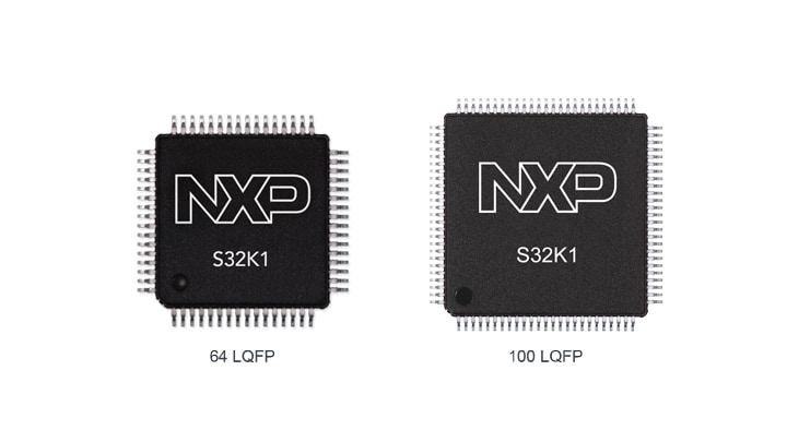
S32K1 Microcontrollers for Automotive General Purpose

Ultra-Reliable MPC564xB-C MCU for Automotive and Industrial Control Applications
| | | | | |
|---|---|---|---|---|---|
| | | | | |
| | | | | |
| | | | | |
| | | | | |
| | | | | |
| | | | | |
| | | | | |
| | | | | |
| | | | | |
| | | | | |
MPC574xB-C-GQuick reference to our documentation types.
1-10 of 49 documents
Compact List
There are no results for this selection.
Sign in to access authorized secure files. Learn more about secure access rights.
Please wait while your secure files are loading.
1-10 of 49 documents
Compact List
2 design files
Sign in to access authorized secure files. Learn more about secure access rights.
Please wait while your secure files are loading.
2 design files
1-5 of 12 hardware offerings
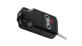

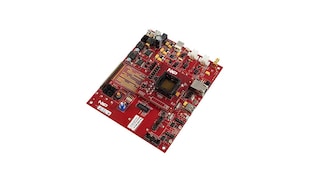
Additional hardware available. View our featured partner solutions.

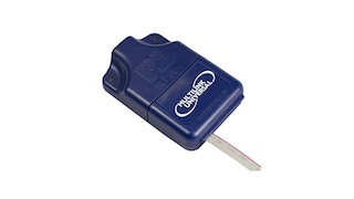
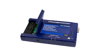
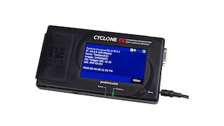
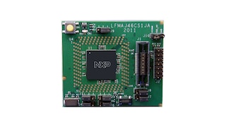

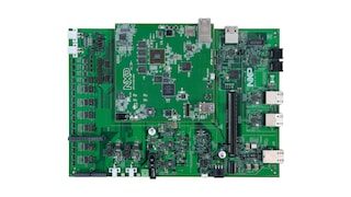
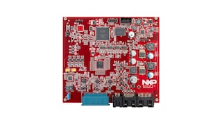
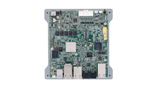
Sign in to access authorized secure files. Learn more about secure access rights.
3 hardware offerings


To find additional partner offerings that support this product, visit our Partner Marketplace.
1-5 of 12 hardware offerings


Additional hardware available. View our featured partner solutions.


Quick reference to our software types.
1-5 of 20 software files
Additional software available. View our featured partner solutions.
Note: For better experience, software downloads are recommended on desktop.
Sign in to access authorized secure files. Learn more about secure access rights.
Please wait while your secure files are loading.
1-5 of 20 software offerings
To find additional partner offerings that support this product, visit our Partner Marketplace.
1-5 of 20 software files
Additional software available. View our featured partner solutions.
Note: For better experience, software downloads are recommended on desktop.
1-5 of 14 engineering services


.svg)


There are no results for this selection.
There are no results for this selection.
To find additional partner offerings that support this product, visit our Partner Marketplace.
5 trainings
Additional trainings are available. View our featured partner trainings.
5 trainings
Additional trainings are available. View our featured partner trainings.
5 trainings
To find additional partner offerings that support this product, visit our Partner Marketplace.
There are no recently viewed products to display.
View or edit your browsing history