- Analog Toolbox
- Getting Started with the P3T1755DP-ARD Evaluation Board
Getting Started with the P3T1755DP-ARD Evaluation Board
Contents of this document
-
Out of the Box
-
Get Hardware
-
Configure the Hardware
Sign in to save your progress. Don't have an account? Create one.

Purchase your P3T1755DP Arduino® Shield Evaluation Board
1. Out of the Box
The NXP analog product development boards provide an easy-to-use platform for evaluating NXP products. The boards support a range of analog, mixed-signal and power solutions. They incorporate monolithic integrated circuits and system-in-package devices that use proven high-volume technology. NXP products offer longer battery life, a smaller form factor, reduced component counts, lower cost, and improved performance in powering state-of-the-art systems.
This page will guide you through the process of setting up and using the P3T1755DP-ARD board.
1.1 Kit Content and Packing List
The P3T1755DP-ARD contents include:
- Assembled and tested evaluation board in an antistatic bag
1.3 Static Handling Requirements
This device is sensitive to ElectroStatic Discharge (ESD). Therefore care should be taken during transport and handling. You must use a ground strap or touch the PC case or other grounded source before unpacking or handling the hardware.
1.4 Minimum System Requirements
- PC Pentium processor (or equivalent)
- One USB port (either 3.0 or 2.0 or 1.1 compatible)
- Windows 7, 8, 10
- MIMXRT685-EVK MCU board (from NXP)
2. Get Hardware
2.1 Board Features
- A complete evaluation platform for the P3T1755DP I³C, I²C-bus, 0.5 °C accuracy, digital temperature sensor
- Easy to use GUI-based software demonstrates the capabilities of the P3T1755DP
- On-board temperature sensor for system thermal management experiments
- Convenient test points for easy scope measurements and signal access
- USB interface to the host PC
- Power supply from USB port (x2) or external power supply can be used to power P3T1755DP-ARD evaluation board
2.2 Board Description
The P3T1755DP-ARD evaluation board features an I³C, I²C-bus, 0.5 °C accuracy, digital temperature sensor. A graphical interface allows the user to easily explore the different functions of the driver. The board can be connected in parallel with other I²C-bus demo boards to create an evaluation system.
The IC communicates to the host via the industry standard I²C-bus port. The evaluation software runs under Microsoft Windows 7, 8, or 10 PC platform.
2.3 Board Components
Overview of the P3T1755DP-ARD board
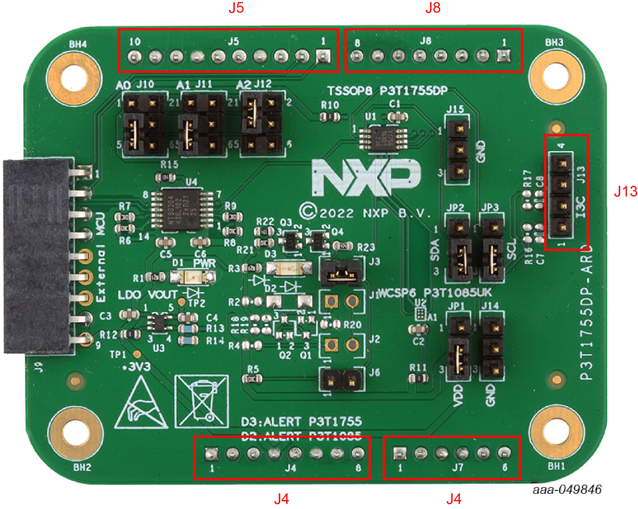
| Device | Description | Location |
|---|---|---|
| P3T1755DP | I³C, I²C-bus, 0.5 °C accuracy, digital temperature sensor | U1 |
| TPS71701DCKT | Adjustable output voltage LDO | U3 |
| NTS0304EPWJ | 4-bit dual supply translating transceiver | U4 |
| Green LED | Power supply on LED | D1 |
| Red LED | Alert LED | D3 |
3. Configure the Hardware
3.1 P3T1755DP-ARD Board and MIMXRT685-EVK MCU Board Connection
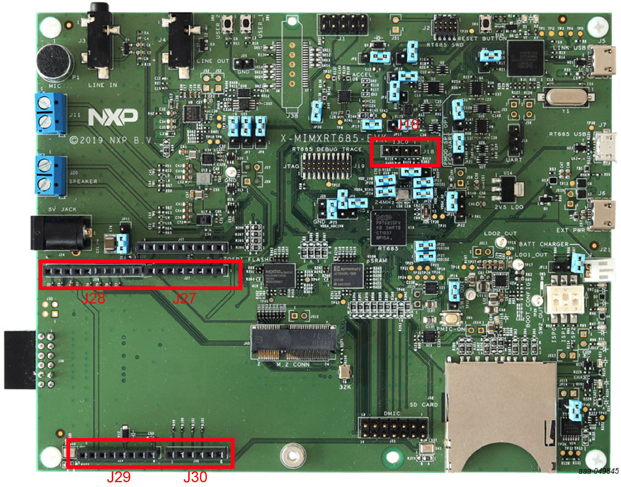
The P3T1755DP-ARD evaluation board is connected to an MIMXRT685-EVK MCU board using four connectors (J4/J5/J7/J8 on P3T1755DP-ARD board and J27/J28/J29/J30 on MIMXRT685-EVK board) for I²C-bus and power supply, and one connector (J18 on P3T1755DP-ARD board and J on MIMXRT685-EVK board) for I³C bus.
The MIMXRT685-EVK MCU board communicates with P3T1755DP-ARD demo GUI through PC USB port and uses I²C or I³C-bus to communicate to P3T1755.
