Getting Started with the FRDM-K32L2B3 Freedom Development Board
Contents of this document
-
Plug It In
-
Get Software
-
Build, Run
-
Modify an SDK Example
Sign in to save your progress. Don't have an account? Create one.
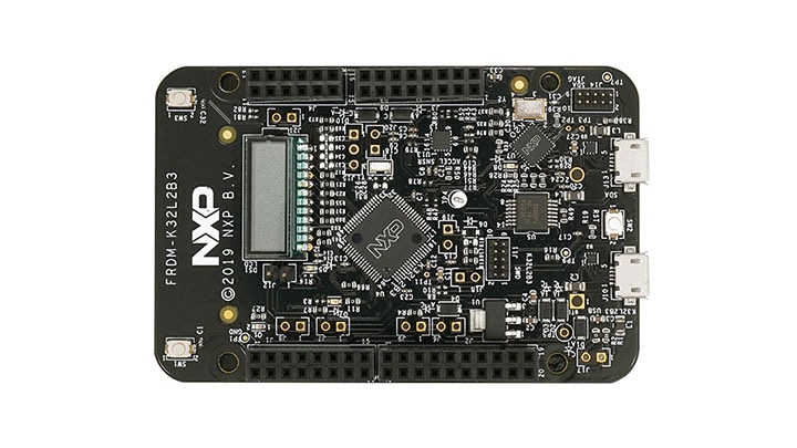
Purchase your FRDM-K32L2B3
1. Plug It In
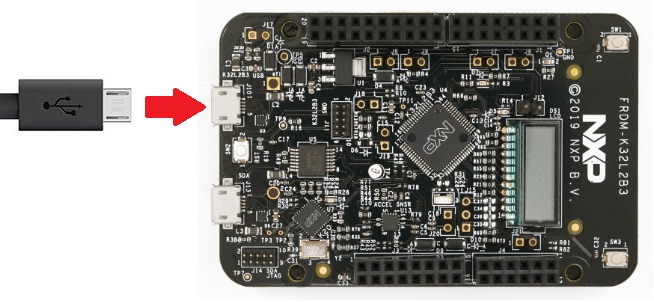
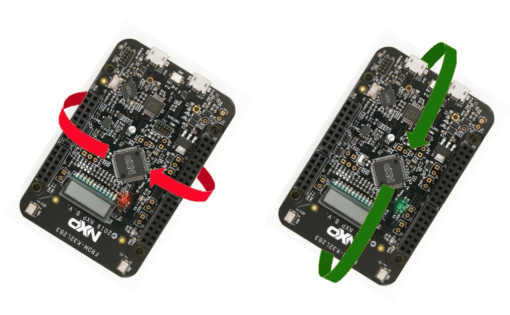
Let's take your FRDM-K32L2B3 for a test drive! You have the choice of watching the sequence in a short video or following the detailed actions listed below.
2. Get Software
2.2 Jump Start Your Design with the MCUXpresso SDK
The MCUXpresso Software Development Kit (SDK) is complimentary and includes full source code under a permissive open-source license for all hardware abstraction and peripheral driver software.
Click below to download a pre-configured Windows SDK release for the FRDM-K32L2B3, which includes IDE support for MCUXpresso, Keil MDK, GCC Arm Embedded and IAR Embedded Workbench.

You can also use the online SDK Builder to create a custom SDK package for the FRDM-K32L2B3.
2.3 Install Your Toolchain
MCUXpresso IDE is a development platform ecosystem from NXP. It provides an end-to-end solution enabling engineers to develop embedded applications from initial evaluation to final production.

Want to use a different toolchain?
No problem, The MCUXpresso SDK includes support for other tools such as IAR , Keil and command-line GCC .

2.4 MCUXpresso Config Tools
The MCUXpresso Config Tools is an integrated suite of configuration tools that guides users in creating new MCUXpresso SDK projects, and also provides pin and clock tools to generate initialization C code for custom board support. It is fully integrated into MCUXpresso or you can download it as a separate tool.
2.5 Serial Terminal
Many of the example applications output data over the MCU UART so you'll want to make sure that the driver for the board's virtual COM port is installed. Before you run the driver installer, you must have the board plugged into your PC.
With the serial port driver installed, run your favorite terminal application to view the serial output from the MCU's UART. Configure the terminal to 115,200 baud rate, 8 data bits, no parity and 1 stop bit. To determine the port number of the FRDM-K32L2B3's virtual COM port, open the device manager and look under the "Ports" group.
Not sure how to use a terminal application? Try one of these tutorials: MCUXpresso IDE Terminal Tutorial, Tera Term Tutorial, PuTTY Tutorial.
3. Build, Run
3.2 Explore the SDK Example Code
The Kinetis SDK comes with a long list of demo applications and driver examples. To see what‘s available, browse to the SDK boards folder of your SDK installation and select your board, the FRDM-K32L2B3: <SDK_Install_Directory>/boards/frdmk32l2b.
To learn more about specific example code, open the readme.txt file in an example’s directory.
3.3 Build, Run
If one or more of the demo application or driver examples sounds interesting, you probably want to know how you can build and debug yourself. The Getting Started with SDK guide provides easy, step-by-step instructions on how to configure, build and debug demos for all toolchains supported by the SDK.
Use the guide below to learn how to open, build and debug an example application using the MCUXpresso IDE.
Running a demo using MCUXpresso IDE
Import the MCUXpresso SDK
- Open the MCUXpresso IDE
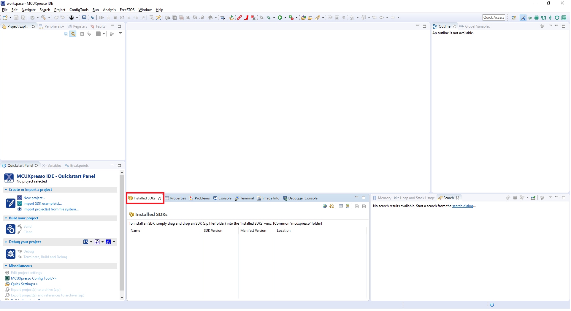
- Switch to the Installed SDKs view within the MCUXpresso IDE window
- Drag and drop the FRDM SDK (zipped) file into the "Installed SDKs" view
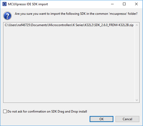
- You will get the following pop-up. Click on "OK" to continue the import:
- The installed SDK will appear in the Installed SDKs view as shown below:

Build an Example Application
The following steps will guide you through opening the hello_world example.
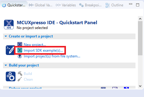
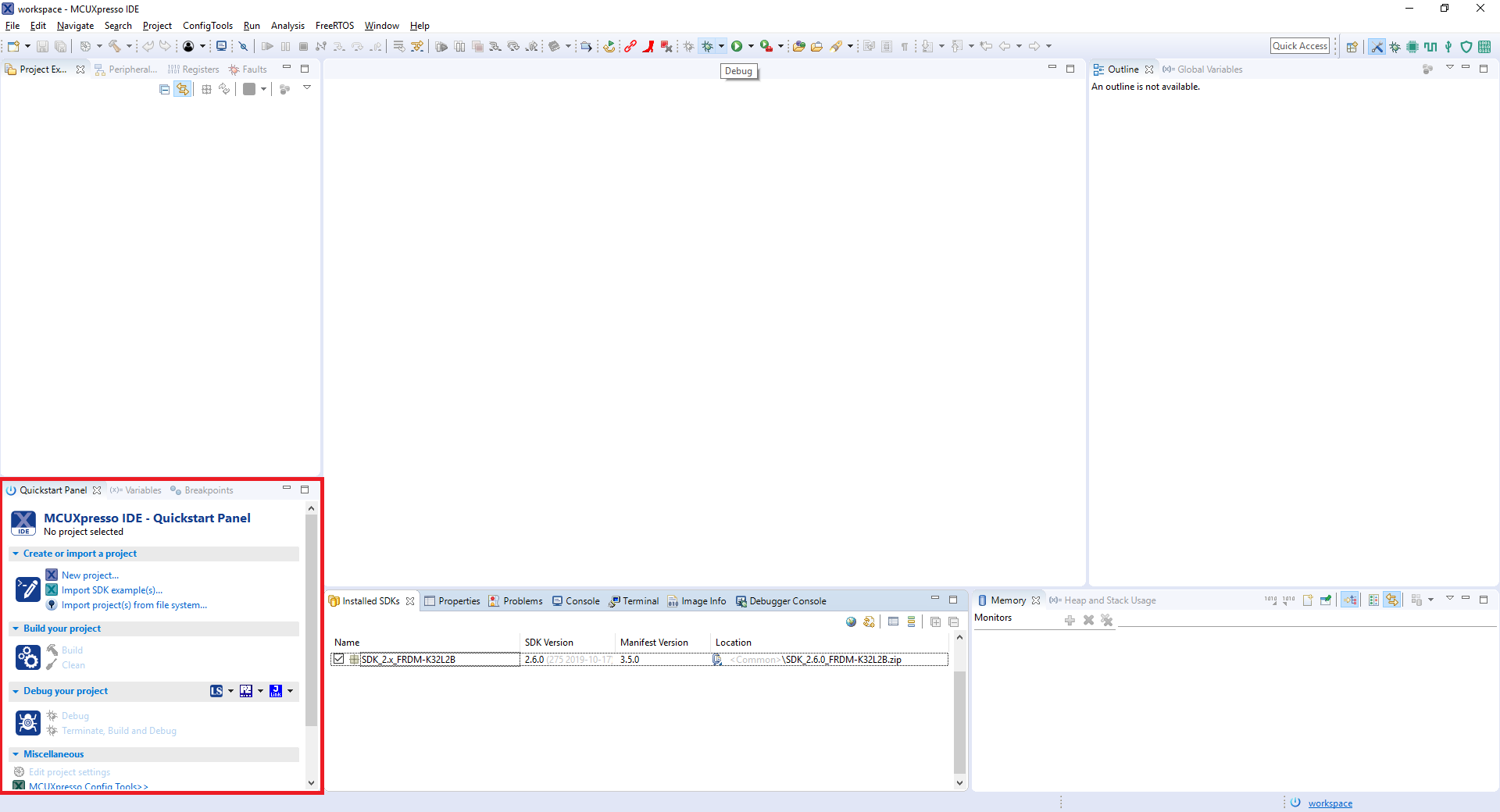
- Find the Quickstart Panel in the lower left-hand corner
- Then click on Import SDK examples(s)
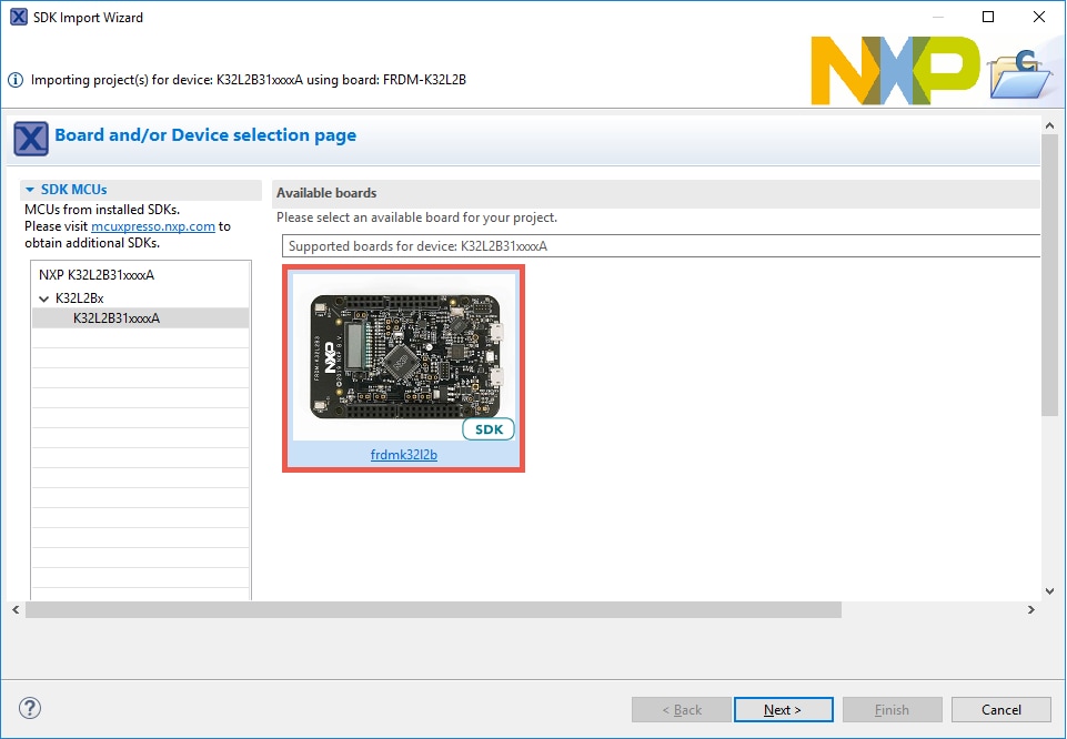
- Click on the frdmk32L2b board to select that you want to import an example that can run on that board, and then click on Next
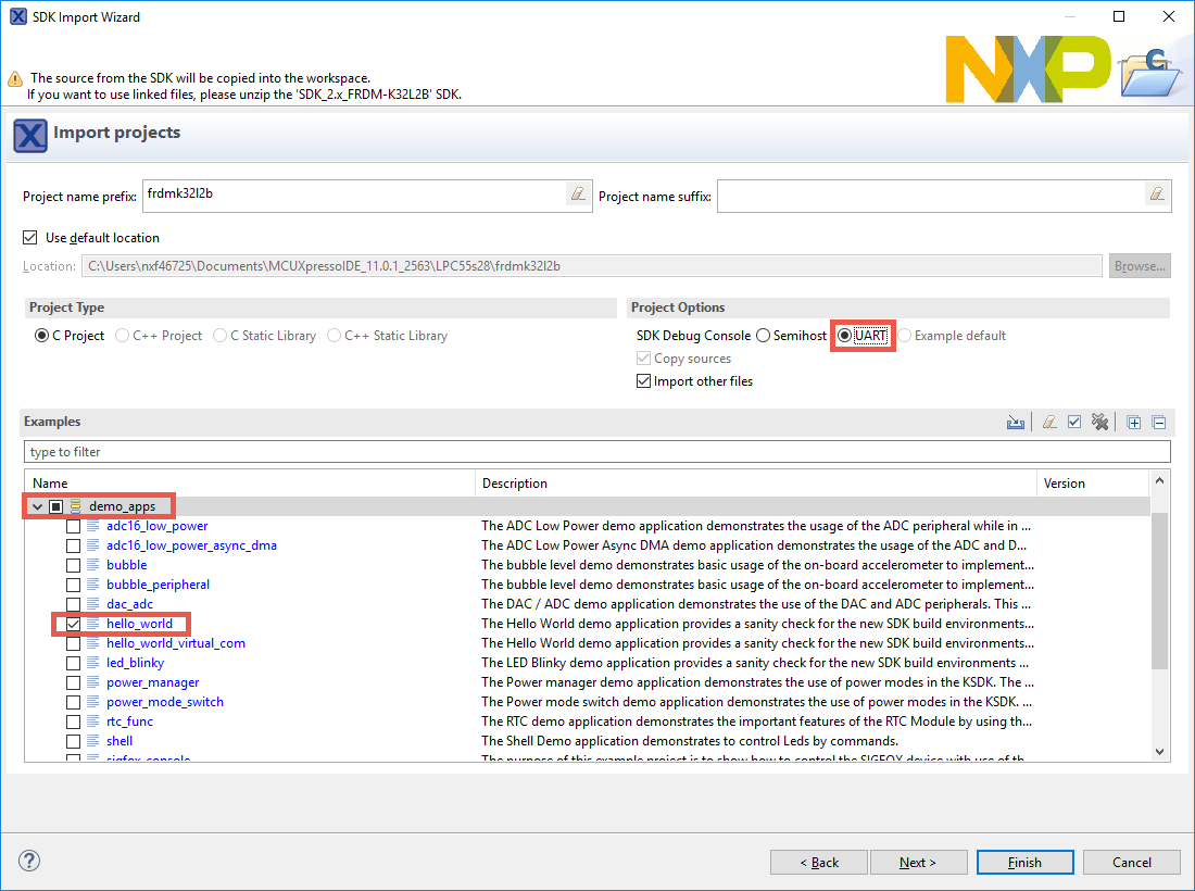
- Use the arrow button to expand the "demo_apps" category, and then click the checkbox next to 'hello_world' to select that project. To use the UART for printing (instead of the default semihosting), Select "UART" as the SDK Debug Console checkbox under the project options. Then, click on "Finish"
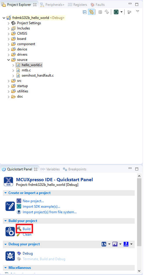
- Now, build the project by clicking on the project name and then in the Quickstart Panel click on Build or press "Ctrl + B"
- You can see the status of the build in the Console tab


Run an Example Application
- Now that the project has been compiled, you can now flash it to the board and run it
- Make sure the FRDM-K32L2B3 board is plugged in and click on "Debug" in the Quickstart Panel
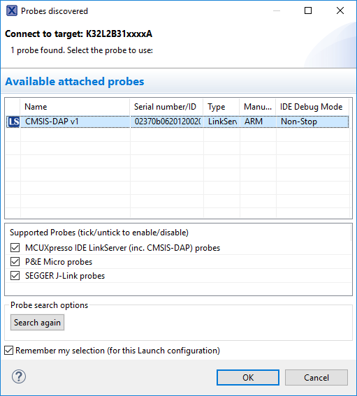
- MCUXpresso IDE will probe for connected boards and should find the MBED CMSIS-DAP debug probe that is part of the integrated OpenSDA circuit on the K32L2B3. Click on OK to continue
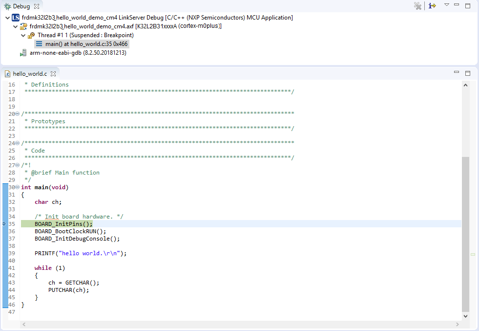
- The firmware will be downloaded to the board, and the debugger started
- Open a terminal program and connect to the COM port the board enumerated as. Configure the terminal with these settings:
- 115,200 baud rate
- No parity
- 8 data bits
- 1 stop bit
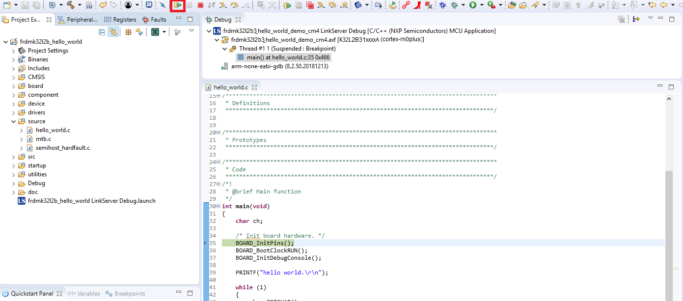
- Start the application by clicking the "Resume" button:
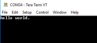
- The hello_world application is now running, and a banner is displayed on the terminal. If this is not the case, check your terminal settings and connections
- Use the controls in the menu bar to pause, step into, and step over instructions and then stop the debugging session by click on the Terminate icon:


Using a different toolchain?
Running a demo using IAR Embedded Workbench IDE
Build an Example Application
The following steps will guide you through opening the hello_world application. These steps may change slightly for other example applications as some of these applications may have additional layers of folders in their path.
- First, unzip the previously downloaded SDK
- If not already done, open the desired example application workspace. Most example application workspace files can be located using the following path:
<install_dir>/boards/<sdk_board_name>/<example_type>/<application_name>/iarUsing the hello_world demo as an example, the path is:
<install_dir>/boards/frdmk32l2b/demo_apps/hello_world/iar - Select the desired build target from the drop-down. For this example, select the "hello_world - Debug" target
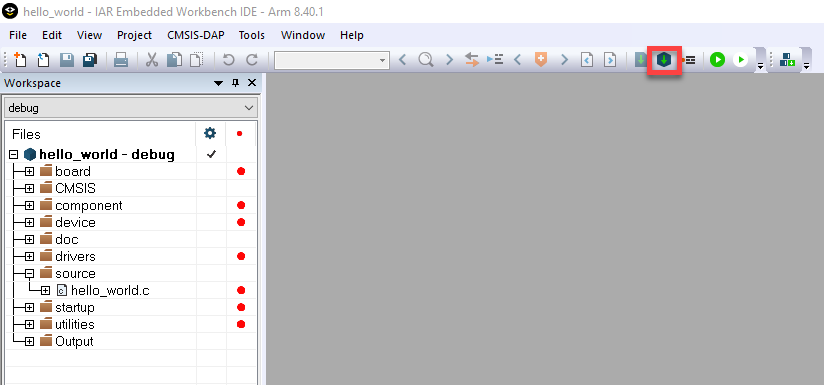
- To build the application, click the "Make" button, highlighted in red below
- The build will complete without errors


Run an Example Application
The FRDM-K32L2B3 board comes loaded with the mbed/CMSIS-DAP debug interface from the factory. If you have changed the debug OpenSDA application on your board, visit OpenSDA for information on updating or restoring your board to the factory state.
- Connect the development platform to your PC via USB cable between the "SDAUSB" USB port on the board and the PC USB connector
- Open the terminal application on the PC (such as PuTTY or Tera Term) and connect to the debug COM port you determined earlier. Configure the terminal with these settings:
- 115,200 baud rate
- No parity
- 8 data bits
- 1 stop bit
- Click the "Download and Debug" button to download the application to the target
- The application is then downloaded to the target and automatically runs to the main () function
- Run the code by clicking the "Go" button to start the application
- The hello_world application is now running, and a banner is displayed on the terminal. If this is not the case, check your terminal settings and connections


Running a demo using Keil® MDK/µVision®
Install CMSIS device pack
After the MDK tools are installed, Cortex® Microcontroller Software Interface Standard (CMSIS) device packs must be installed to fully support the device from a debug perspective. These packs include things such as memory map information, register definitions and flash programming algorithms. Follow these steps to install the appropriate CMSIS pack.
- Open the MDK IDE, which is called µVision. In the IDE, select the "Pack Installer" icon
- In the Pack Installer window, search for "K32L2B3" to bring up the K32L2B3 family. Click on the K32L2B3 name, and then in the right-hand side you'll see the NXP::FRDM-K32L2B_DFP pack. Click on the "Install" button next to the pack. This process requires an Internet connection to successfully complete
- After the installation finishes, close the Pack Installer window and return to the µVision IDE


Build the Example Application
The following steps will guide you through opening the hello_world application. These steps may change slightly for other example applications as some of these applications may have additional layers of folders in their path.
- If not already done, open the desired demo application workspace in:
<install_dir>/boards/<sdk_board_name>/<example_type>/<application_name>/mdkThe workspace file is named <application_name>.uvmpw, so for this specific example, the actual path is:
<install_dir>/boards/frdmk32l2b3/demo_apps/hello_world/mdk/hello_world.uvmpw - To build the demo project, select the "Rebuild" button, highlighted in red
- The build will complete without errors

Run an Example Application
The FRDM-K32L2B board comes loaded with the mbed/CMSIS-DAP debug interface from the factory. If you have changed the debug OpenSDA application on your board, visit OpenSDA for information on updating or restoring your board to the factory state.
- Connect the development platform to your PC via USB cable between the "SDAUSB" USB port on the board and the PC USB connector
- Open the terminal application on the PC (such as PuTTY or Tera Term) and connect to the debug COM port you determined earlier. Configure the terminal with these settings:
- 115,200 baud rate
- No parity
- 8 data bits
- 1 stop bit
- After the application is properly built, click the "Download" button to download the application to the target
- Click on "Start/Stop Debug Session" to open the debug view
- Run the code by clicking the "Run" button to start the application
- The hello_world application is now running, and a banner is displayed on the terminal. If this is not the case, check your terminal settings and connections


4. Modify an SDK Example
4.2 Clone an Example Project from MCUXpresso SDK
Option A: Use the MCUXpresso IDE to clone an example project.
Use MCUXpresso IDE
Build an Example Application
The following steps will guide you through opening the GPIO led output. This example takes turns to shine the led.
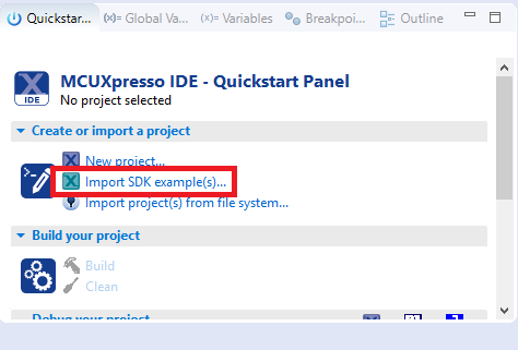
- Find the Quickstart Panel in the lower left-hand corner
- Then click on Import SDK examples(s)
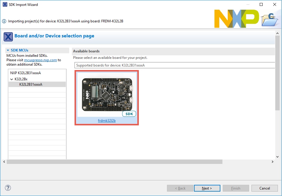
- Click on the frdmk32l2b board to select that you want to import an example that can run on that board, and then click on Next
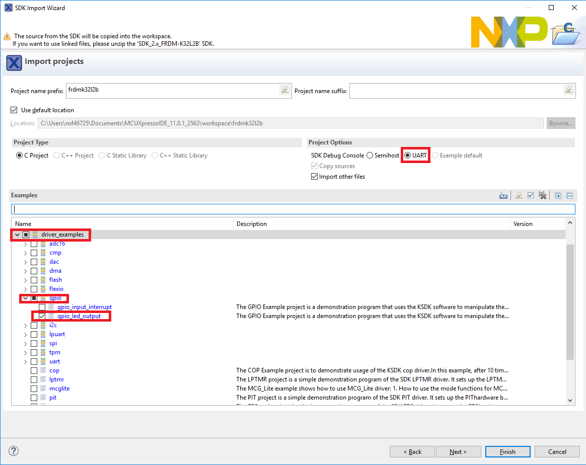
- Use the arrow button to expand the "driver_examples" category, then expand the "GPIO" examples, click on the checkbox next to "gpio_led_output" to select it. To use the UART for printing (instead of the default semihosting), select UART as the SDK Debug Console checkbox under the project options. Then, click on "Finish"
- Click on the "frdmk32l2b_gpio_led_output" project in the Project Explorer view and build, compile and run the demo as described previously
- You should see the LEDs blinking on the board
- Terminate the debug session

Option B: Use the MCUXpresso Config Tool to clone an existing MCUXpresso SDK example for use with third party IDEs.
Use MCUXpresso Config Tools
The following steps will guide you through opening the GPIO led output. This example takes turns to shine the led.
- Open the MCUXpresso Config Tools
- In the wizard that comes up, select the "Create a new configuration based on an SDK example or hello word project" radio button and click on Next
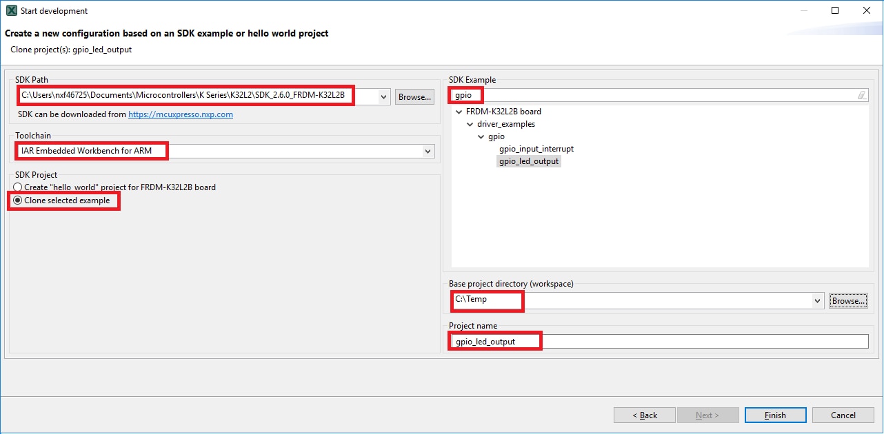
- On the next screen, select the location of the MCUXpresso SDK that you had unzipped earlier. Then select the IDE that is being used. Note that only IDEs that were selected in the online SDK builder when the SDK was built will be available and click on clone select example
- Then select the project to clone. For this example, we want to use the GPIO led output project. You can filter for this by typing "GPIO" in the filter box and then selecting the "gpio_led_output" example project. You can then also specify where to clone the project and the name. Then click on Finish
- After cloning go to the directory you selected and open the project for your IDE. Import, compile and run the project as done in previous sections
- You should see the LEDs blinking on the board
- Terminate the debug session

4.3 Use the Pins Tool
Now, let’s use the Pins Tool that is part of the MCUXpresso Config Tools to show how to add a new GPIO pin to your project to blink an LED.
Use MCUXpresso IDE Pins Tool
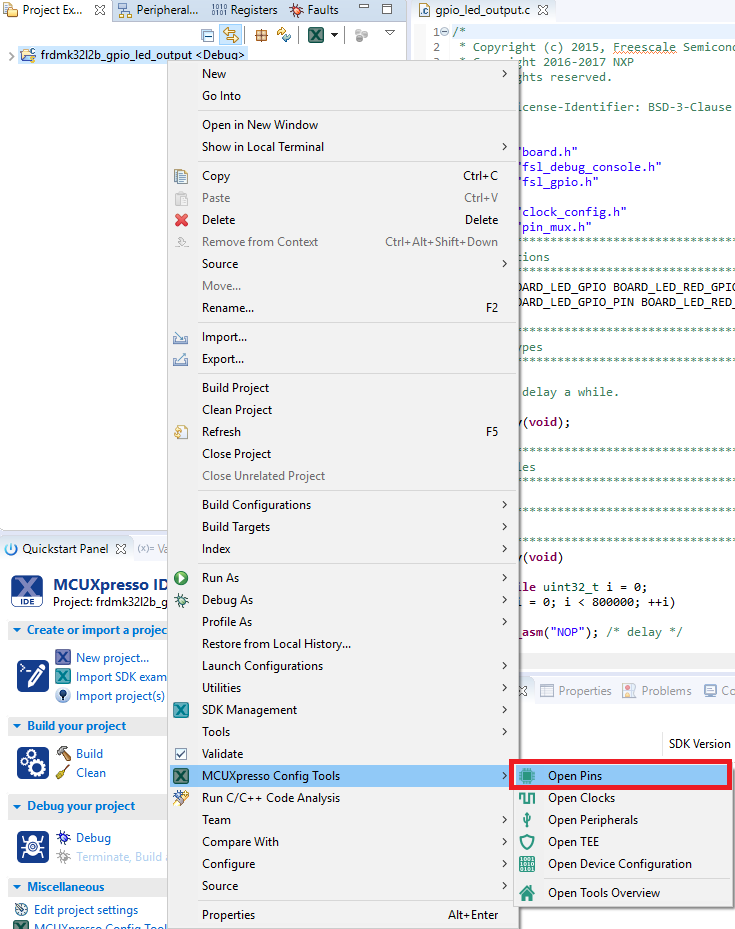
Open Pins Tool in MCUXpresso IDE
- Open the pins tool by right clicking on the "frdmk32l2b_gpio_led_output" project, and selecting "MCUXpresso Config Tools" and then "Open Pins"
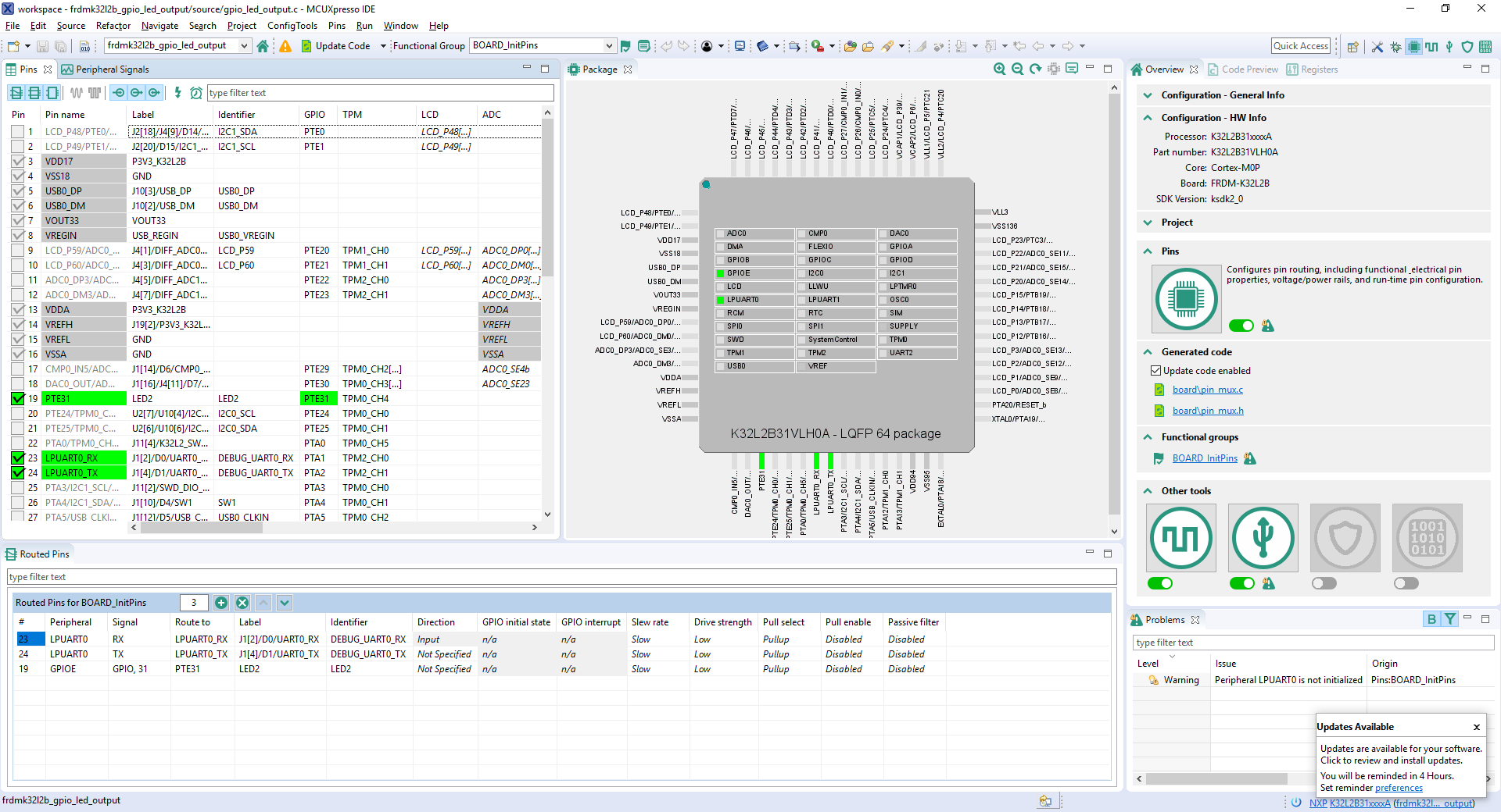
- The Pins Tool should now display the pin configuration for the PWM project
Open Pins Tool in MCUXpresso Config Tools
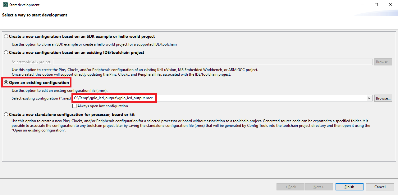
- Open the MCUXpresso Config Tool
- In the wizard that comes up, select the "Open existing configuration" radio button, then select the project that you had clone and click on Next
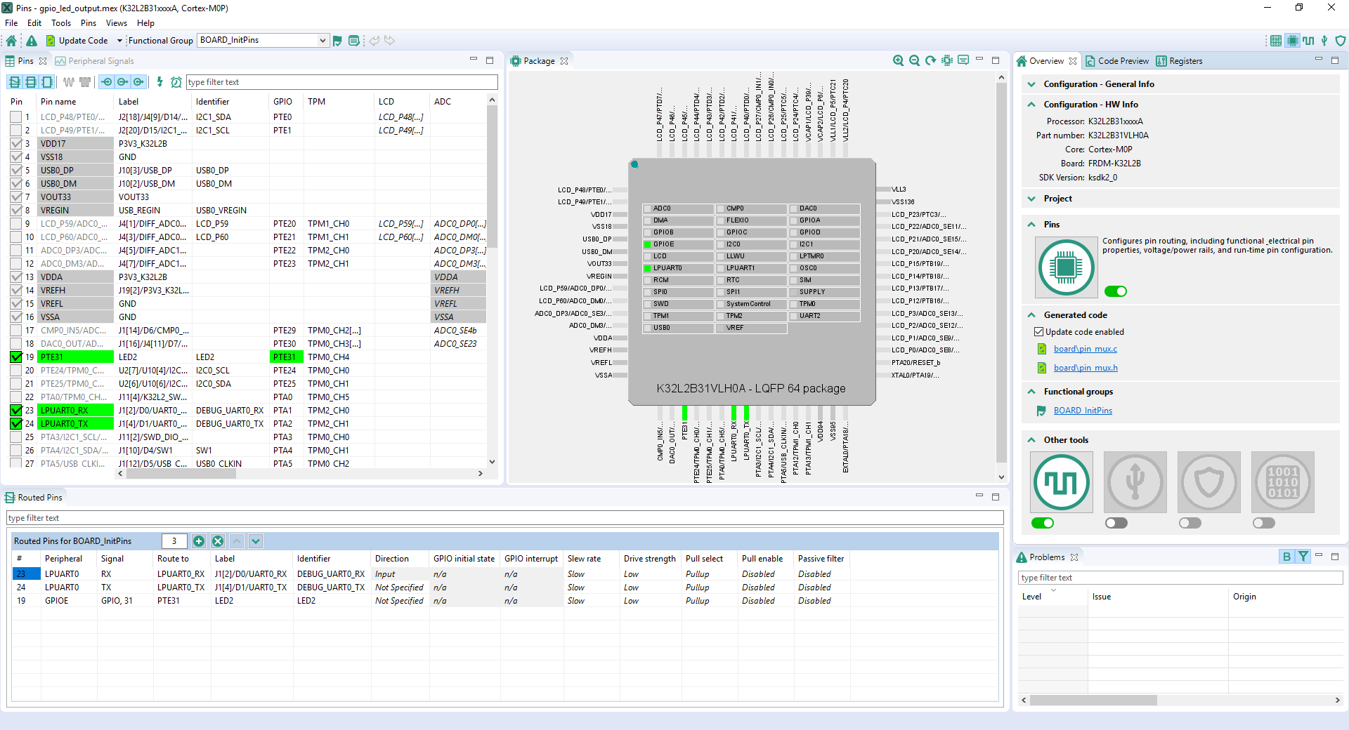
- Open the Pins Tool by selecting Tools → Pins from the toolbar
- The pins tool should now display the pin configuration for the PWM project

Use the Pins Tool to modify the GPIO routed pin
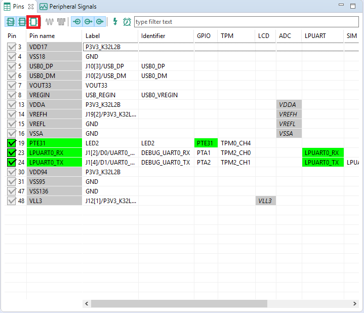
- We'll use MCUXpresso IDE for the rest of the instructions, but the same steps can be done in MCUXpresso Config Tools for third party IDEs. In the Pins view deselect the "Show not routed pins" checkbox to see only the routed pins, you also going to see the pins that are routed by default. Routed pins have a check in a green box next to the pin name. The functions selected for each routed pin are highlighted in green
- In the current configuration,
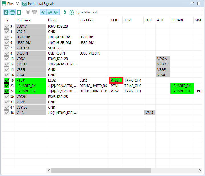
PTE31is routed as a GPIO toggle the red LED. For this example, we'll usePTD5instead to drive the green LED - Disable,
PTE31as a GPIO by clicking thePTE31field under the GPIO column. The pin will then be disabled (pin will no longer have check in box) and thus disappear from the list - Now, route
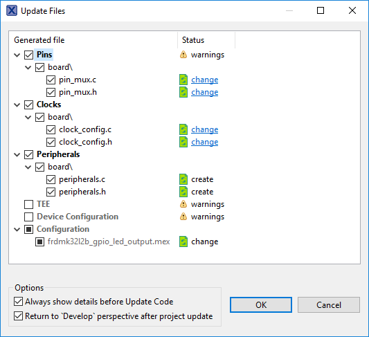
PTD5as a GPIO. First, select the "Show not routed pins" so that all the pins are displayed again. Then, searchPTD5in the Pins view. Finally, click the box under the GPIO columnPTD5. The box will highlight in green, and a check will appear next to the pin - Now it's time to implement these changes into the project by exporting the new updated pin_mux.c and pin_mux.h files that are generated by the Pins Tool. Click on Update Project in the menu bar
- The screen that pops up will show the files that are changing and you can click on "diff" to see the difference between the current file and the new file generated by the Pins Tool. Click on "OK" to overwrite the new files into your project
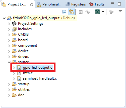
- Now inside the IDE, open the gpio_led_output.c file
- Change two #defines to tell the GPIO project to use the new
PTD5pin. Change from the red LED to the green - Build and download the project as done in the previous section
- Run the application. You will now see the green LED blink!
- Terminate the debug session



4.4 Use the Clocks Tool
Next, use the Clocks Tool that is part of the MCUXpresso Config Tools to change the clock settings and change the rate that the LED blinks.
Use MCUXpresso IDE Clocks Tool
Open Clocks Tool in MCUXpresso IDE
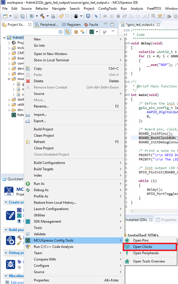
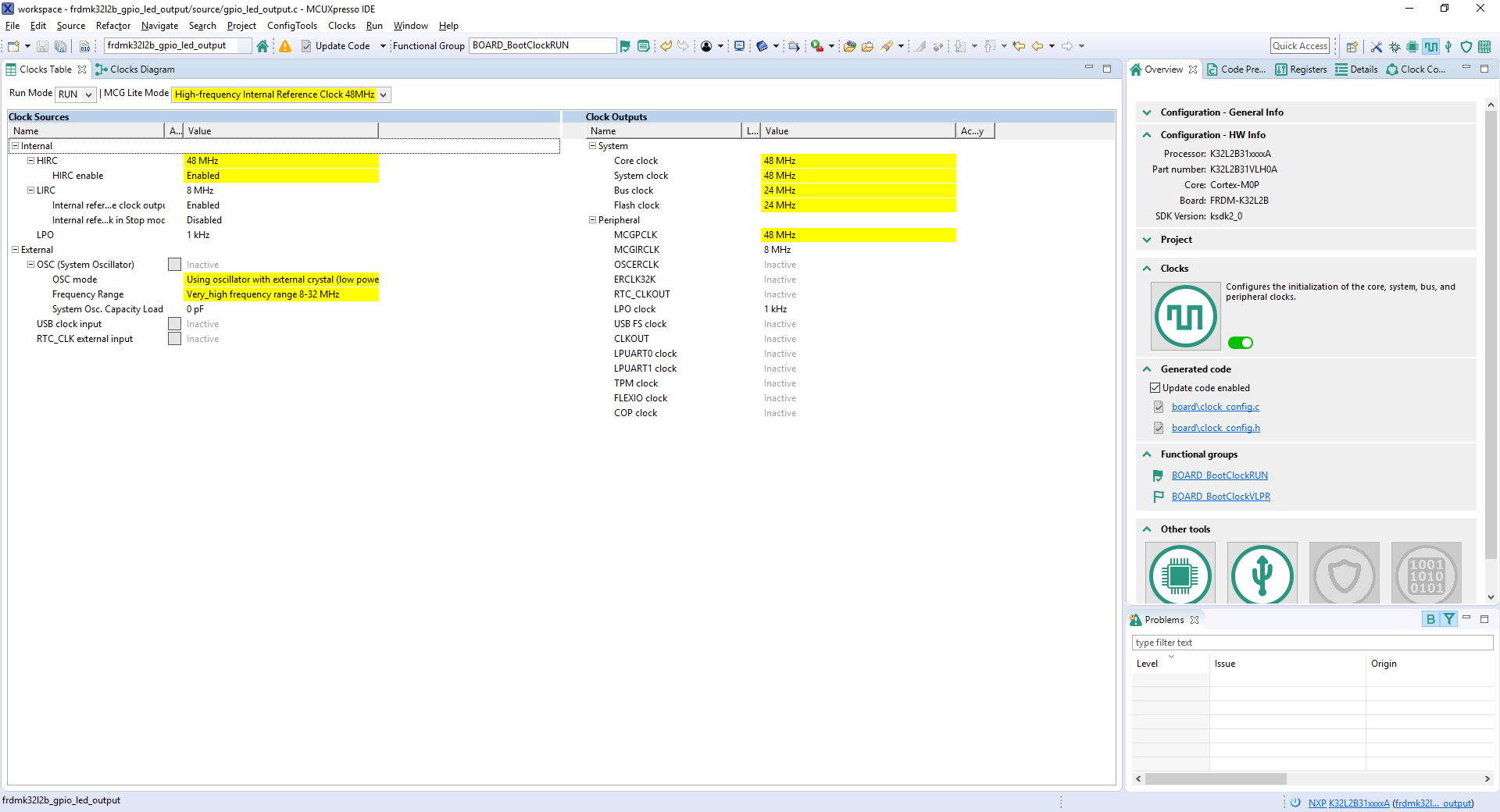
- Open the Clocks Tool by right clicking on the "frdmk32l2b_gpio_led_output" project and selecting "MCUXpresso Config Tools" and then "Open Clocks"
- The Clocks Tool should now display the pin configuration for the project
Open Clocks Tool in MCUXpresso Config Tools
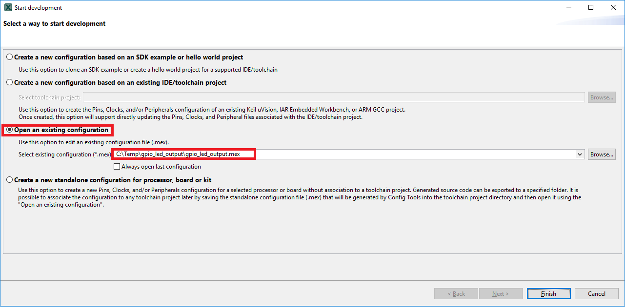
- Open the MCUXpresso Config Tools
- In the wizard that comes up, select the "Open existing configuration" radio button, then select the project that you had clone and click on Next
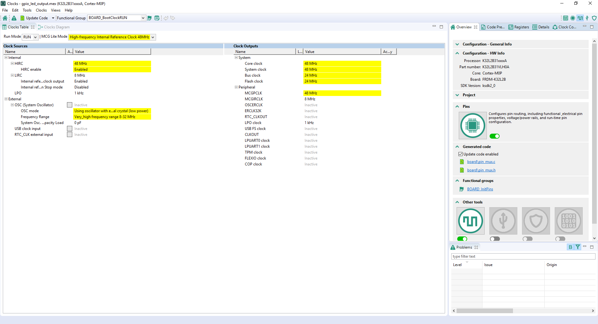
- Open the Clocks Tool by selecting Tools → Clocks from the toolbar
- The Clocks Tool should now display the clock configuration for the PWM project

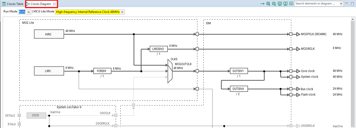
Use the Clocks Tool to modify the System Clock
- We'll use MCUXpresso IDE for the rest of the instructions, but the same steps can be done in MCUXpresso Config Tools for third party IDEs. Switch to the Clocks Diagram view by clicking the tab in the upper left corner
- Make sure that you are in the functional group called "BOARD_BootClockRun"
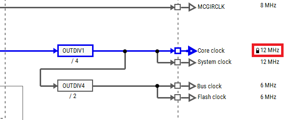
- Change the core clock frequency by clicking in the "Core Clock" field and typing "12". You'll see all the other clock values automatically change as well to adjust to this slower speed. It will look like this when done:
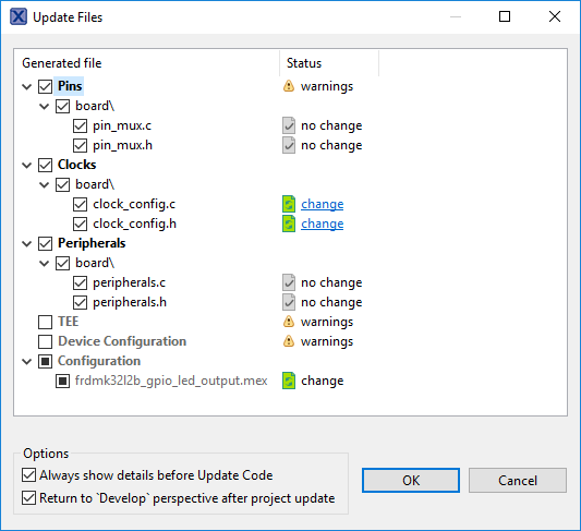
- Now it's time to implement these changes into the project by exporting the new updated clock_mux.c and clock_mux.h files that are generated by the Clocks Tool. Click on Update Project in the menu bar
- The screen that pops up will show the files that are changing, and you can click on "diff" to see the difference between the current file and the new file generated by the Clocks Tool. Click on "OK" to overwrite the new files into your project
- Build and download the project as done in the previous section
- Run the application. The green LED should now be blinking at a much slower rate!
- Terminate the debug session


MCUXpresso IDE Terminal Tutorial
MCUXpresso IDE Terminal Tutorial
The most recent versions of MCUXpresso IDE count with a terminal emulation application. This tool can be used to display information sent from your NXP development platform's virtual serial port.
- Open the MCUXpresso IDE
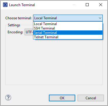
- Launch the MCUXpresso IDE terminal by clicking on the "Open a Terminal" button on the top of the IDE or press "Ctrl + Alt + Shift + T"
- Select Serial Terminal
- Configure the serial port settings (using the corresponding COM port number) to 115,200 baud rate, 8 data bits, no parity and 1 stop bit, then press "OK" button
- Verify that the connection is open. If connected, MCUXpresso IDE will look like the figure below at the Terminal view
- You're ready to go




Tera Term Tutorial
Tera Term Tutorial
Tera Term is a very popular open source terminal emulation application. This program can be used to display information sent from your NXP development platform's virtual serial port.
- Download Tera Term from SourceForge. After the download, run the installer and then return to this webpage to continue
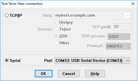
- Launch Tera Term. The first time it launches, it will show you the following dialog. Select the serial option. Assuming your board is plugged in, there should be a COM port automatically populated in the list
- Configure the serial port settings (using the COM port number identified earlier) to 115,200 baud rate, 8 data bits, no parity and 1 stop bit. To do this, go to Setup → Serial Port and change the settings
- Verify that the connection is open. If connected, Tera Term will show something like below in its title bar

PuTTY Tutorial
PuTTY Tutorial
PuTTY is a popular terminal emulation application. This program can be used to display information sent from your NXP development platform's virtual serial port.
- Download PuTTY using the button below. After the download, run the installer and then return to this webpage to continue
- Launch PuTTY by either double clicking on the *.exe file you downloaded or from the Start menu, depending on the type of download you selected
- Configure in the window that launches, select the Serial radio button and enter the COM port number that you determined earlier. Also enter the baud rate, in this case: 115,200
- Click Open to open the serial connection. Assuming the board is connected, and you entered the correct COM port, the terminal window will open. If the configuration is not correct, PuTTY will alert you
- You're ready to go


Security and Integrity
Security and Integrity
| Document | Description |
|---|---|
| AN4507 Using the Kinetis Security and Flash Protection Features | Using the system security and flash protection features on Kinetis MCUs to protect code and data from unauthorized access or modification. |
Wired Communications
Wired Communications
| Document | Description |
|---|---|
| Understanding FlexIO | The FlexIO module is capable of emulating various serial communication protocols including UART, SPI and I²C. |
| AN12174 Using FlexIO to emulate communications and timing peripherals | A compilation of examples to emulate different communication modules and PWM signals using FlexIO. |
| AN5034 Emulating UART by Using FlexIO | How to use the universal peripheral module FlexIO for emulating an additional UART bus. |
| AN5397 Emulating SSI Using FlexIO | How to configure FlexIO to emulate a Serial Synchronous Interface. |
| AN4955 Emulating the I2S Bus Master with the FlexIO Module | Shows a typical use case for the FlexIO peripheral – emulating I2S for transferring an audio data stream. |
| AN5133 Emulating I²C Bus Master by using FlexIO | The steps to use the FlexIO module for emulating the I²C bus master. |
| AN5242 Emulating Dual SPI Using FlexIO | One example of how to use the FlexIO module to emulate the dual SPI of both master and slave mode at the same time. |
| AN12597 USB to Multi VCOM on K32L2 Series MCU | How to implement a USB to multiple VCOMs' functions on K32L2 series FRDM boards. |
MCUXpresso SDK Examples
Several examples, demos and drivers are available within the SDK to help you get started. Some common examples for wired communications are listed below.
Bubble Demo (I²C example)
Demonstrates basic usage of the onboard accelerometer to implement a bubble level. A bubble level utilizes two axes to visually show deviation from a level plane (0 degrees) on a given axis.
Path: <SDK_PATH>/boards/frdmk32l2b/demo_apps/bubble
Shell Demo (UART example)
Demonstrates how to implement a command line shell application.
Path:
<SDK_PATH>/boards/frdmk32l2b/demo_apps/shell
Driver Examples
A number of driver examples exist within the SDK including FlexIO, I²C, SPI and UART.
Path:
<SDK_PATH>/boards/frdmk32l2b/driver_examples
USB Examples
These examples are built on and demonstrate various USB classes and provide jumping off points for your application.
Path:
<SDK_PATH>/boards/frdmk32l2b/usb_examples
Wireless Connectivity
Wireless Connectivity
| Document | Description |
|---|---|
| AN5116 Emulating IrDA by Using FlexIO | How to use FlexIO SDK UART driver to emulate IrDA. |
MCUXpresso SDK Examples
Several examples, demos and drivers are available within the SDK to help you get started. Some common examples for wireless connectivity are listed below.
NTAG I²C Explorer Blink
Shows use of NT3H2111_2211 NTAG I²C plus Connected NFC Tag with I²C Interface Chip and demonstrates basic communication with the device.
Path: <SDK_PATH>/boards/frdmk32l2b/ntag_i2c_plus_examples/ntag_i2C_explorer_blink
NTAG I²C Explorer Demo
Shows use of NT3H2111_2211 NTAG I²C plus Connected NFC Tag with I²C Interface Chip and demonstrates communication with the device in SRAM pass through mode and external application.
Path: <SDK_PATH>/boards/frdmk32l2b/ntag_i2c_plus_examples/ntag_i2C_explorer_demo
Sigfox Console
How to control the Sigfox device with use of the Sigfox SW driver built on AML (Analog Middleware Layer). It uses the virtual serial console to execute SPI commands of the Sigfox device.
Path: <SDK_PATH>/boards/frdmk32l2b/demo_apps/sigfox_console
Power Management
Power Management
| Document | Description |
|---|---|
| AN12736 K32L2B Power Mode Switch Application | Shows details of each power mode and provides use case examples in the SDK power mode switch example demo. Tips are given for using each of the power modes. |
| AN4503 Power Management for Kinetis MCUs | When and how to use Kinetis low-power modes. |
MCUXpresso SDK Examples
Several examples, demos and drivers are available within the SDK to help you get started. Some common examples for power management are listed below.
Power Mode Switch Demo
Demonstrates the use of power modes in the SDK.
Path: <SDK_PATH>/boards/frdmk32l2b/demo_apps/power_mode_switch
Power Manager Demo
How to change power modes in the SDK.
Path: <SDK_PATH>/boards/frdmk32l2b/demo_apps/power_manager
ADC Low Power Demo
Demonstrates the usage of the ADC peripheral while in a low power mode.
Path: <SDK_PATH>/boards/frdmk32l2b/demo_apps/adc16_low_power
ADC Low Power Async DMA Demo
Demonstrates the usage of the ADC and DMA peripheral while in a low power mode.
Path: <SDK_PATH>/boards/frdmk32l2b/demo_apps/adc16_low_power_async_dma
RTC Demo
Demonstrates the important features of the RTC Module by using the RTC peripheral driver.
Path: <SDK_PATH>/boards/frdmk32l2b/demo_apps/rtc_func
Audio
Audio
| Document | Description |
|---|---|
| AN4955 Emulating the I2S Bus Master with the FlexIO Module | Shows a typical use case for the FlexIO peripheral – emulating I2S for transferring an audio data stream. |
MCUXpresso SDK Examples
Several examples, demos and drivers are available within the SDK to help you get started. Some common examples for audio are listed below.
DSP examples
CMSIS DSP examples are provided to demonstrate CMSIS DSP driver usage in the SDK environment.
Path: <SDK_PATH>/CMSIS/DSP/Examples/ARM
Audio Demos
Examples that enumerate a recording device.
Path: <SDK_PATH>/boards/frdmk32l2b/usb_examples/usb_device_audio_generator
Path: <SDK_PATH>/boards/frdmk32l2b/usb_examples/usb_device_composite_hid_audio
Display and Graphics
Display and Graphics
| Document | Description |
|---|---|
| AN12579 Using SLCD controller on K32L2B3 MCU | Describes the usage of the on-chip SLCD controller by enabling an SLCD device. |
| NXP FlexIO Generator for the WS2812B (Adafruit NeoPixel) LED Stripe Protocol | Example project to drive WS2812B LEDs using the FlexIO module. |
Support
Trainings
| Training | Description |
|---|---|
| K32 L Series Trainings | Full list of on-demand training, how-to videos and webinars from NXP about this product. |
| Basic Application Development Using MCUXpresso IDE and MCUXpresso Config Tools | This three-part video series covers the basic interactions between the MCUXpresso IDE and Config Tools when working with either an imported SDK example project or creating a new one. |
On this page
- 1.1
Getting Started with the FRDM-K32L2B3
- 1.2
Get Familiar with the Board
- 1.3
Attach the USB Cable
- 1.4
Run the Out-of-the-Box Demo
- 2.1
Installing Software for the FRDM-K32L2B3
- 2.2
Jump Start Your Design with the MCUXpresso SDK
- 2.3
Install Your Toolchain
- 2.4
MCUXpresso Config Tools
- 2.5
Serial Terminal


