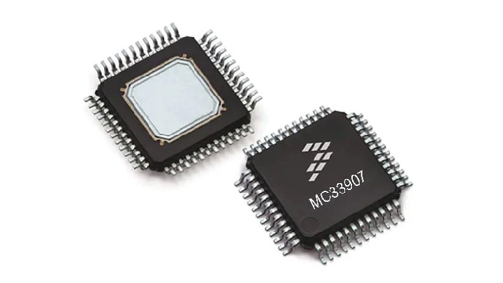
Safe System Basis Chip DC/DC up to 800 mA
Sign in for a personalized NXP experience.
The MPC564xA family of MCUs offers enhanced powertrain functionality and addresses the harsh environments of mid-range gasoline and direct injection engines, advanced transmissions, and industrial applications.
| | | | | |
|---|---|---|---|---|---|
| | | | | |
| | | | | |
| | | | | |
| | | | | |
| | | | | |
| | | | | |
| | | | | |
| | | | | |
| | | | | |
| | | | | |
Quick reference to our documentation types.
1-10 of 41 documents
Compact List
There are no results for this selection.
Sign in to access authorized secure files. Learn more about secure access rights.
Please wait while your secure files are loading.
1-10 of 41 documents
Compact List
1 design file
Sign in to access authorized secure files. Learn more about secure access rights.
Please wait while your secure files are loading.
1 design file
1-5 of 12 hardware offerings

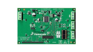
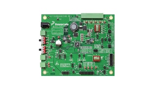
Additional hardware available. View our featured partner solutions.

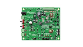


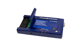
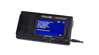
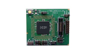


Sign in to access authorized secure files. Learn more about secure access rights.
2 hardware offerings
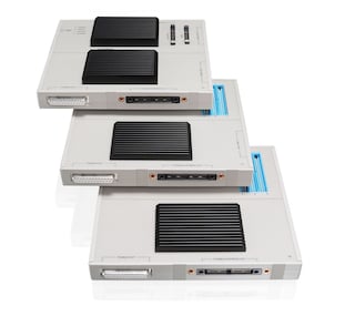

To find additional partner offerings that support this product, visit our Partner Marketplace.
1-5 of 12 hardware offerings


Additional hardware available. View our featured partner solutions.


Quick reference to our software types.
1-5 of 25 software files
Additional software available. View our featured partner solutions.
Note: For better experience, software downloads are recommended on desktop.
Sign in to access authorized secure files. Learn more about secure access rights.
Please wait while your secure files are loading.
1-5 of 12 software offerings
To find additional partner offerings that support this product, visit our Partner Marketplace.
1-5 of 25 software files
Additional software available. View our featured partner solutions.
Note: For better experience, software downloads are recommended on desktop.
1-5 of 11 engineering services


.svg)


There are no results for this selection.
There are no results for this selection.
To find additional partner offerings that support this product, visit our Partner Marketplace.
1-5 of 8 trainings
To find additional partner offerings that support this product, visit our Partner Marketplace.
8 trainings
To find additional partner offerings that support this product, visit our Partner Marketplace.
There are no recently viewed products to display.

Help us improve your experience on our site. We invite you to take our five-question survey.