Getting Started with the KITPF8200FRDMPGM
Contents of this document
-
Get Started
-
Get to Know the Hardware
-
Configure Hardware
-
Install Software
Sign in to save your progress. Don't have an account? Create one.

Purchase your PF8200/PF8100 Programming Board
1. Get Started
The NXP analog product development boards provide an easy-to-use platform for evaluating NXP products. The boards support a range of analog, mixed-signal and power solutions. They incorporate monolithic integrated circuits and system-in-package devices that use proven high-volume technology. NXP products offer longer battery life, a smaller form factor, reduced component counts, lower cost and improved performance in powering state-of-the-art systems.
This page will guide you through learning about how to set up the KITPF8200FRDMPGM programming board.
1.1 Kit Contents and Packing List
Working with the KITPF8200FRDMPGM requires the kit contents, additional hardware and a Windows PC workstation with installed software.
Kit Contents
- Assembled and tested KITPF8200FRDMPGM and preprogrammed FRDM-KL25Z microcontroller board in an antistatic bag
- 3.0 ft USB-STD A to USB-B-mini cable
- USB to mini USB cable
- Quick Start Guide
2. Get to Know the Hardware
2.1 Board Overview
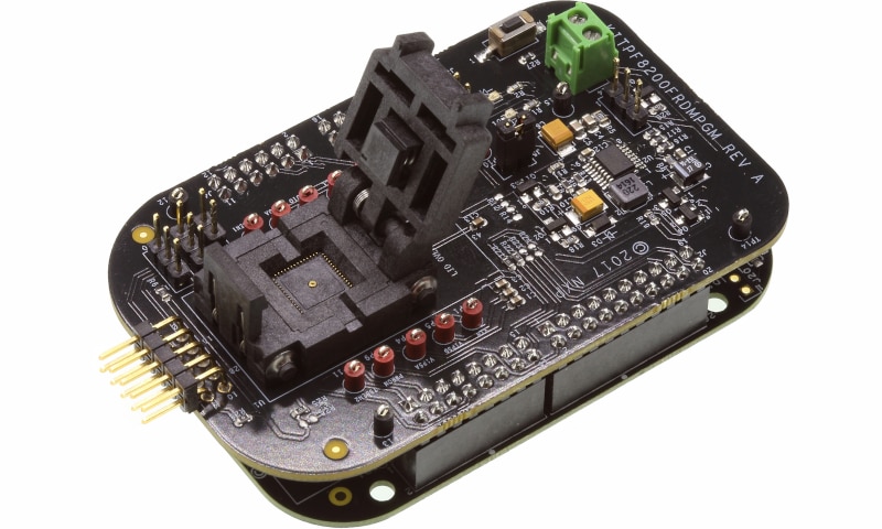
The KITPF8200FRDMPGM programming board provides an easy-to-use platform for programming NXP products. The NXP OTP programming boards provide an easy-to-use platform for programming the default configuration of the NXP PF81/82 power management products. The boards support all voltages and signals needed for OTP programming.
The KITPF8200FRDMPGM is a programming board that provides the user with information to program the PF81/82 multi-channel power management integrated circuit.
2.2 KITPF8200FRDMPGM Programming Board Features
Programming Socket
- Clamshell 56-pin QFN socket
System Features
- 5.0 V operating input voltage range (from USB connector)
- Integrated boost converted to supply VDDOTP programming voltage
- USB to I²C communication via the FRDM-KL25Z interface
- Inline programming interface connector
Attached FRDM-KL25Z
The Freedom KL25Z is an ultra-low-cost development platform for Kinetis® L Series KL1x (KL14/15) and KL2x (KL24/25) MCUs built on Arm® Cortex®-M0+ processor.
Features include: Easy access to MCU I/O, battery-ready, low-power operation, a standards-based form factor with expansion board options and a built-in debug interface for flash programming and run-control.
3. Configure Hardware
3.1 Configure the Hardware
This section summarizes the overall setup. A detail description is provided in the User Guide.
Suggested equipment’s needed for test:
- Computer
- Mini USB type A Cable

3.3 Device Considerations
It is recommended to learn about the devices and their specifications prior to operating the boards. The device has a high level of flexibility due to parameter configuration available in the OTP. This impacts the functionality of the device. It is key to understand how the parameters are programmed on each device.
3.4 Setting Up the Board
Configure the hardware and workstation as illustrated.
-
Plug the KITPF8200FRDMPGM board on top of the FRDM-KL25Z board
- For standalone chip programming: introduce a PF8x QFN device in the socket (ensure pin 1 is properly aligned)
- For inline programming: connect the interface connector to the system board and ensure that VIN power is provided either from the programmer or at the system board. Ensure that
SCLandSDApins are connected only to the PMIC and isolated from the system bus to avoid the unpowered system from pulling down/up the signal causing communication problems
-
Connect the USB cable from the PC to the USB port on the Freedom board
- Verify that the board is receiving power (green LED is lit)
- Press the "Reset" button on the Freedom board, to ensure that the board is properly recognized
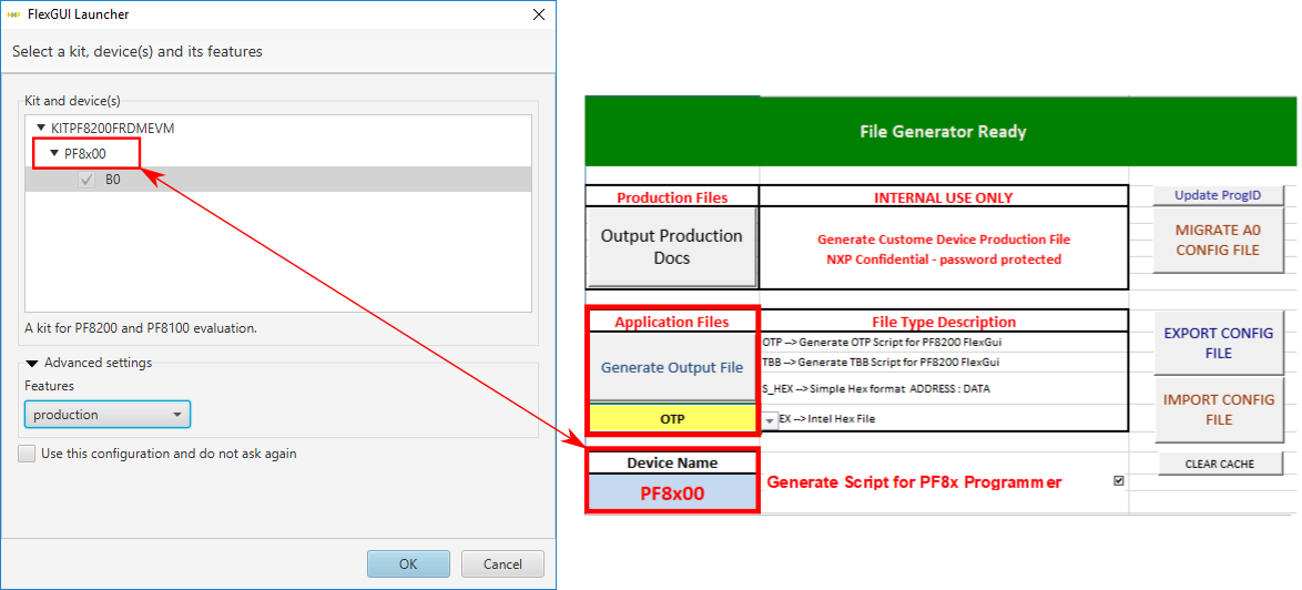
3.5 Generating OTP Configuration
- Choose the desired OTP configuration using the corresponding "PF8xxx Custom OTP Request Form" file provided in the "Scripts" and "Forms" folder. Make sure to use the correct form and device number matching the samples to be programmed
- Ensure that the device name is set to the same device in the FlexGUI launcher to generate the correct commands to interface with the FlexGUI script editor
- Generate an OTP script using the file generation section on the OTP request form. Make sure to fill all required fields marked with a "*" to enable the file generation. Also, select the "PF8x Programmer" option to generate the proper code for OTP programming using the KITPF8200FRDMPGM programmer
- Save the generated OTP file in a known location
4. Install Software
4.1 Preparing the Graphical User Interface Operating Environment
Download and run SW for the KITPF8200FRDMPGM programming board. These evaluation boards use FlexGUI software for the PF8100/PF8200 device. Prior to the installation of the FlexGUI software and performing device firmware updates (if needed), download and unzip the NXP_FlexGUI_PF8x_REV_0.7.x.zip file to any desired location.
4.2 Installing the Java JRE
- Download Java JRE (Java SE Runtime Environment), available at Java Downloads (8u162 or newer)
- Open the installer and follow the installation instructions
- Following the successful installation, restart the computer
4.3 Installing FlexGUI Software Package
The FlexGUI software installation requires only extracting the zip file in a desired location.
- If necessary, install the Java JRE and Windows 7 FlexGUI driver
- Download the latest FlexGUI (32-bit or 64-bit) version, NXP_FlexGUI_PF8x_REV_0.7.x.zip, available at KITPF8200FRDMPGM
- Extract all the files to a desired location on your PC
FlexGUI is started by running the batch file: NXP_FlexGUI_PF8x_Rev_0.7.x\NXP FlexGUI\bin\flexgui-app-pf8xxxx.bat. The FlexGUI Rev 0.7.0 or higher, interfaces with the FRDM-KL25Z Freedom board via USB-HID protocol, which should be recognized automatically by the Windows OS eliminating the need for any extra hardware drivers. See "UM11162: Section 4.4 'Updating the PF81/82 FlexGUI firmware'" for details on how to install or update the FRDM-KL25Z, in case the board is not loaded with the latest firmware and USB-HID support.
4.4 Updating the PF8100/PF8200 FlexGUI Firmware
The FRDM-KL25Z Freedom board is used as a communication bridge to interface the FlexGUI with the PMIC and other I²C devices. The firmware is organized in three levels:
- At first level, the SDA uses the BOOTLOADER to operate as the main path to flash the functional code of the SDA processor. The BOOTLOADER is preprogrammed on the FRDM-KL25Z Freedom boards and cannot be reflashed to avoid permanent damage to the Freedom board
- At second level, the SDA provides a firmware loader for drag and drop update of the KL25Z MCU firmware
- At the third level, the KL25Z MCU provides the FlexGUI firmware in charge of converting the USB communication into MCU instructions to control digital I/Os as well as I²C communication to the PMIC. If the FRDM-KL25Z is not loaded with the correct firmware to support a future software upgrade, the firmware can be updated in a few simple steps
4.5 Flashing the FRDM-KL25Z Firmware Loader
- Press the pushbutton on the Freedom board and connect the USB cable into the
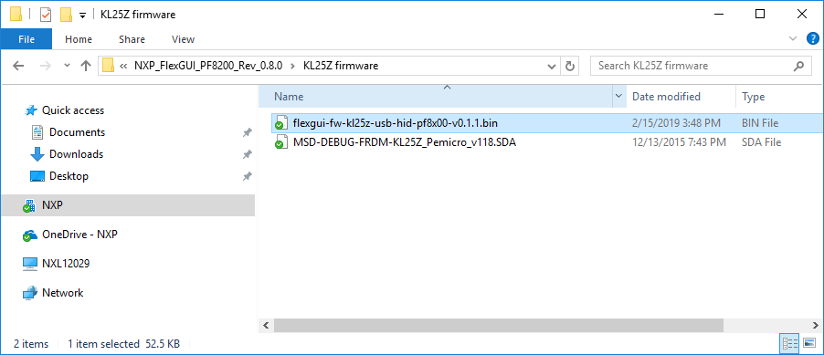
SDAport on the Freedom board. A new BOOTLOADER device should appear on the left pane of the file explorer - Drag and drop the file
MSD-DEBUG-FRDM-KL25Z_Pemicro_v118.SDAinto the BOOTLOADER drive. The file should be located in the "KL25Z firmware" folder - Disconnect and reconnect the USB cable into the
SDAport (this time without pressing the pushbutton). A new device called "FRDM_KL25Z" is installed on the PC


4.6 Flashing the FlexGUI Firmware
If a new software or silicon release requires a firmware update on the FRDM-KL25Z Freedom board, use the following procedure to upgrade or downgrade the firmware of the Freedom board as needed. Note that this procedure is needed only to update the firmware and may be skipped if no change is needed.
- Connect the USB cable in the
SDAport (without holding the pushbutton) - Locate the ".bin" FlexGUI driver to be installed, for example
flexgui-fw-kl25z-usb-hidpf8x00-v0.1.1.bin, drag and drop the file into the FRDM_KL25Z driver - Freedom board firmware is successfully loaded
Design Resources
Additional Resources
Product Summary Pages
- PF8100/PF8200: Power Management Integrated Circuit (PMIC) for high-performance processing applications
- PF8101/PF8201: 9- channel Power Management Integrated Circuit (PMIC) for high-performance processing applications
- PF8121: 12 – channel Power Management Integrated Circuit (PMIC) for high-performance processing applications
Tool Summary Page
The tool summary page for the KITPF8200FRDMPGM is at KITPF8200FRDMPGM. This page provides overview information, technical and functional specifications, ordering information, documentation and software. The Getting Started guide provides quick-reference information applicable to using the KITPF8200FRDMPGM programming board, including the downloadable assets.
Hardware Pages
Software Pages
On this page
- 3.1
Configure the Hardware
- 3.2
Configuration Image
- 3.3
Device Considerations
- 3.4
Setting Up the Board
- 3.5
Generating OTP Configuration