Getting Started with the FRDMGD31ECNEVM Evaluation Kit
Contents of this document
-
Out of the Box
-
Plug It In
-
Configure Hardware
-
Get Software
Sign in to save your progress. Don't have an account? Create one.

Purchase your FRDMGD31ECNEVM | Half-Bridge Evaluation Kit
1. Out of the Box
The NXP analog product development boards provide an easy-to-use platform for evaluating NXP products. The boards support a range of analog, mixed-signal and power solutions. They incorporate monolithic integrated circuits and system-in-package devices that use proven high-volume technology. NXP products offer longer battery life, a smaller form factor, reduced component counts, lower cost and improved performance in powering state-of-the-art systems.
This page will guide you through the process of setting up and using the FRDMGD31ECNEVM board.
1.1 Kit Contents/Packing List
The FRDMGD31ECNEVM contents include:
- Assembled and tested FRDMGD31ECNEVM board in an anti-static bag
- FRDM-KL25Z connected to translator board (3.3 V to 5.0 V)
- Cable, USB type A male/type mini B male 3 ft
- Quick Start Guide
1.2 Additional Hardware
In addition to the kit contents, the following hardware is necessary or beneficial when working with this kit.
- IGBT or SiC MOSFET module in EconoDUAL™ package
- DC link capacitor compatible with IGBT or SiC MOSFET module
- 50 mil jumpers for configuration
- 50 µH, high current air core inductor for double pulse testing
- HV power supply with protection shield and hearing protection
- 25 V, 1.0 A DC power supply
- Pulse generator
- TEK MSO 4054 500 MHz 2.5 GS/s 4-channel oscilloscope
- Rogowski coil, PEM Model CWT Mini HF60R or CTW MiniHF30 (smaller diameter)
- Two isolated high voltage probes (CAL Test Electric CT2593-1, LeCroy AP030)
- Four low voltage probes
- Two digital voltmeters
2. Plug It In
2.1 Board Features
- Capability to connect to MOSFET or IGBT modules with an EconoDUALTM footprint for half-bridge evaluations
- Daisy chain SPI communication capable
- Power supply and fail-safe jumper configurable
- Easy access power, ground and signal test points
2.2 Board Description
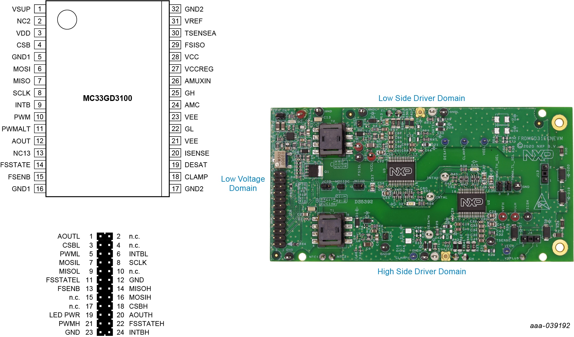
The FRDMGD31ECNEVM is a half-bridge evaluation kit populated with two GD3100 single channel IGBT gate drive devices on a half-bridge evaluation board with pin configuration compatible with Econo IGBTs.
The kit includes the Freedom KL25Z microcontroller hardware for interfacing a PC installed with SPIGen software for communication to the SPI registers on the GD3100 gate drive devices in either daisy chain or standalone configuration.
2.3 3.3 V to 5.0 V Translator Board
GD3100 translator enables level shifting of signals from 3.3 V to 5.0 V SPI communication.


3. Configure Hardware
3.1 Configure the Hardware for Startup
The following figure presents a typical hardware configuration.

To configure the hardware and workstation, complete the following procedure:
- Connect FRDM-KL25Z and the translator board with FRDMGD31ECNEVM half-bridge evaluation board by attaching to the 24-pin header in the correct orientation
- Attach the FRDMGD31ECNEVM to an IGBT module as desired with socket pins firmly on the module pin connections. Half-bridge board jumpers will be pre-installed from the factory and configured for SPI communication in a non-daisy chain SPI configuration
- Attach 12 V DC power supply to VPWR connection on half-bridge board and low voltage domain GND test point connection on half-bridge board. Note: Be sure to ground to low voltage domain for VPWR connection.
- Connect USB cable from USBKL25Z USB mini connection to Windows-based PC USB port. KL25Z will be pre-installed with firmware from factory
- With SPIGEN GUI installed and application running on Window-based PC, reconnect USB cable. A pop-up should appear indicating connection to the FRDM-KL25Z board
- Enable the 12 V DC power supply to the VPWR low voltage domain. The SPIGEN GUI enables you to READ and WRITE registers on each GD3100 gate driver on either SPI0 (low-side) or SPI1 (high-side)
- Observe VCCL and VCCH voltage levels on the low-side and high-side high voltage domains respectively. These are set to provide the gate drive high levels from the fly-back transformers and are isolated from the low voltage domain and from each other and have isolated grounds. VCCL (low-side) and VCCH (high-side) will be at ~17 V with VEE set to ~-3.3 V, which will be the swing levels of the gate driver PWM signals
- With a DC link voltage supplied and an inductive load connected to the IGBT module, double pulse and short-circuit testing can be performed utilizing the SPIGEN pulse test functions in conjunction with the FRDMGD31ECNEVM half-bridge evaluation board. Use test points to observe desired signals
4. Get Software
4.1 Preparing Graphical User Interface Operating Environment
-
Install the firmware and MCU code
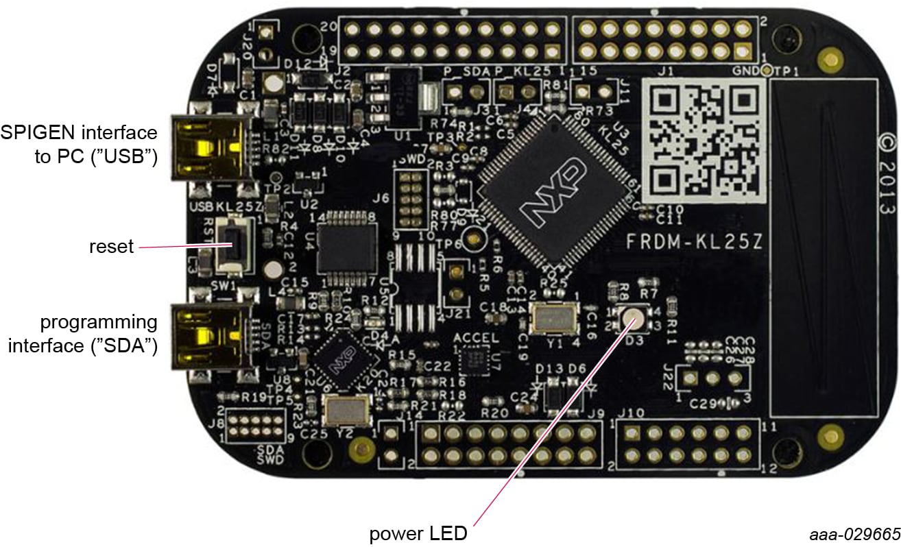
- The kit ships with KL25Z MCU firmware already installed. If for any reason the KL25Z MCU firmware needs
to be re-installed, follow this procedure. Hold down the reset button on the KL25Z board and connect a
mini USB B cable from the PC to the programming interface SDA USB port. Release the reset button. The PC
shows a drive called
E:/BOOTLOADERor something similar. Copy the SDA file (MSD- DEBUG-FRDM-KL25Z_Pemicro_v118.SDA) to theE:/BOOTLOADERdrive - Unplug and re-plug the USB cable to the same location to restart and activate the new firmware (do not
hold the reset button this time). The drive name changes to
E:/FRDM-KL25Zor something similar. Copy the file UsbSpiDongleKL25Z_GD3100_545.srec to theE:/FRDM-KL25Zdrive. Unplug USB cable. Firmware files are available with SPIGEN install, which can be downloaded from NXP.com and can be found in SPIGEN install directory folder
- The kit ships with KL25Z MCU firmware already installed. If for any reason the KL25Z MCU firmware needs
to be re-installed, follow this procedure. Hold down the reset button on the KL25Z board and connect a
mini USB B cable from the PC to the programming interface SDA USB port. Release the reset button. The PC
shows a drive called
- Run SPIGEN SPI generator software installer to install SPIGEN on PC
-
Run SPIGEN with KL25Z board connected
- Connect the PC to the mini USB B cable into the “USBKL25Z” USB port on the KL25Z board
- Open the SPIGen software on the PC. At the bottom of the page, you should see SPI dongle Firmware Ver. 5.4.7 or later
