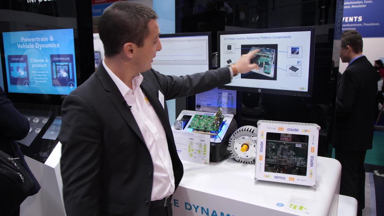
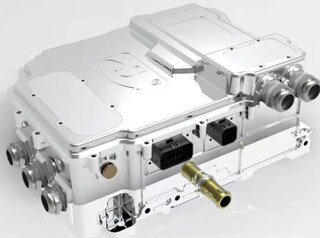
EV Power Inverter Control Reference Platform Gen 1

Roll over image to zoom in

Block Diagram

Choose a diagram:

HEV/EV Motor Control

RDPWRINVERTER-BD

Inverter Platform HW and SW

Inverter Platform HW and SW

Supported Devices

Processors and Microcontrollers

Ultra-Reliable MPC57xx MCUs

Power Management

System Basis Chips

Powertrain and Engine Control

Interfaces

3.3 V / 5 V IO CAN Transceivers

Features

Functionality

  • The multicore 32-bit MCU with the included software provides advanced motor control timing with integrated software resolver
  • Efficiently drives 100 kW 3-phase motor from a 400 V supply
  • Integrated galvanic signal isolation in IGBT gate drivers
  • Redundant CAN-bus interface with low power standby
  • Supported by S32DS IDE SDK with MCAL drivers
  • Gate driver with less than 2us iSense compatible 2 level IGBT overcurrent protection with soft shutdown

Interfaces

  • CAN connectivity support

Security

  • Multicore 32-bit MCU with Hardware Security Module compliant to SHE

Functional Safety and Reliability

  • Robust fail-silent SBC with AEC-Q100 grade 0 capability targeting ASIL D
  • Multicore 32-bit Lockstep MCU with AEC Q100 grade 1 targeting ASIL D
  • Functional safety case and enablement software with API
  • Targeting ASIL D compliance with small, compact 9 IC system footprint

Enablement Kit (EV-INVERTER)

  • Contains four PCBs, cabling and basic three phase software to enable quick development of your in-house inverter design using a complete NXP solution.
  • Software will be provided to allow for system configuration and basic control of a three-phase inverter for driving a permanent magnetic synchronous motor (PMSM) or induction motor.

MCU Control Board (EV-CONTROLEVM)

  • For each of the boards included in the enablement kit, hardware schematics, PCB layouts and gerber files will be available on the NXP website for download.
  • This board contains three key NXP integrated circuits. The MPC5775E is a 32-bit Power Architecture© dual core MCU with lock step offers performance up to 264 MHz/core, CSE security, eTPU timers and a highly scalable solution. The FS65 system basis chip (SBC) provides power to the MCU optimizes energy consumption and provides low voltage side monitoring and protection. The TJA1042 transceiver for high-speed CAN applications in the automotive industry provides the differential transmit and receive capability to the MPC5775E and a CAN protocol controller.

Driver Control Board (EV-POWEREVB)

  • This board is designed for the Fuji M653 IGBT 6-pack inverter module. It features the GD3100 advanced single-channel gate driver for IGBTs and SiC MOSFETs with integrated galvanic isolation and low on-resistance drive transistors. It provides high charging and discharging current, low dynamic saturation voltage and rail-to-rail gate voltage control. In addition, it autonomously manages severe faults and reports faults and status via INTB pin and an SPI interface. Gate voltage is supplied via isolated transformers and a flyback controller.

Sensor Board (EV-SENSOREVB)

  • The sensor board has three identical LEM® HC5F900 current sensors for motor phase current sensing. This board is intended to be used with EV-CONTROLEVB_MCU Control board.

Interface Board (EV-INTERFACEVB)

  • The interface board houses the 23 position Ampseal® connector for external logic power supply, communication and signals from the motor. The board employs line filters and protection circuitry for each signal. This board is intended to be used together with EV-CONTROLEVB_MCU Control board.

PCB Interconnect cables (EV-HW-INVERTER)

  • Includes cables and hardware to interconnect the four boards.

Software Drivers

  • Basic software will be provided to allow for easy system configuration and driving a three-phase inverter for motor control.

Vepco

  • As a service to our customers, we developed a complete platform with a third party including the four boards, IGBT module, DC link capacitor, bus bar, cooling plate, motor, case and custom software. This platform is available through Vepco Technologies Inc.

Inverter Specifications

  • Operating input range: 250-420 VDC
  • Output power: 95 kW continuous, 196 kW peak
  • Nominal voltage: 320 VDC
  • Nominal current: 300 A, rms / peak current: 470 A, rms
  • Motor operating speed: 0–10 k RPM
  • PWM switching frequency: 3–12 kHz
  • Maximum electrical efficiency: > 96 %

System Control

  • Efficiently drives 100 kW 3-phase motor from a 400 V supply
  • Redundant CAN bus interface with low power standby
  • Integrated galvanic signal isolation in IGBT gate drivers

Size

  • Small footprint: ASIL D 100 kW power inverter enablement
  • Inverter mechanical envelope: 28 x 28 x 14 cm
  • Inverter mass: < 10 Kg

Motor Configuration

  • 3 Phase 8 Pole SRPMa
  • Voltage / Power
    • Operating voltage: 250 - 600 VDC, nominal 600 VDC
    • Peak current: 450 A rms
  • Peak output power: 150@30s kW
  • Torque / Speed
    • Continuous 135 Nm, Peak 300 Nm
  • Max 12,000@30s RPM, base speed 6,400 RPM

Motor Sensors

  • Resolver mechanical position sensor

Motor Size

  • Resolver mechanical position sensor

Access to Development Suite Includes

  • NXP device collateral: MPC55775E, GD3100, FS65, TJA1051-Datasheets, erratas, functional safety document and software drivers
  • Enablement kit hardware design collateral: Reference design schematics (PDF), gerber files, BOM, user manual
  • Basic software: Basic software with service level, SDK, drivers and software user manual outlining installation
  • System safety package (in development)

Buy Options

EV-INVERTER-Image

Click to expand

  • EV-INVERTER
    Active

  • EV Power Inverter Control Reference Platform Gen 1.

  • $6900.00 USD
  • For a quantity of 1
Order from distributors

Documentation

Quick reference to our documentation types.

5 documents

Training

2 trainings

Support

What do you need help with?