Getting Started with the KITPF7100FRDMPGM
Contents of this document
-
Out of the Box
-
Plug it in
-
Get Software
-
Configure Hardware
Sign in to save your progress. Don't have an account? Create one.

Purchase your KITPF7100FRDMPGM | PF7100 OTP Programming Board
1. Out of the Box
The NXP analog product development boards provide an easy-to-use platform for evaluating NXP products. The boards support a range of analog, mixed-signal and power solutions. They incorporate monolithic integrated circuits and system-in-package devices that use proven high-volume technology. NXP products offer longer battery life, a smaller form factor, reduced component counts, lower cost and improved performance in powering state-of-the-art systems.
This page will guide you through the process of setting up and using the KITPF7100FRDMPGM evaluation board.
1.1 Kit Contents/Packing List
The KITPF7100FRDMPGM contents include:
- Assembled and tested evaluation board and preprogrammed FRDM-KL25Z microcontroller board in an anti-static bag
- USB-STD A to USB-B-mini cable
- Quick Start guide
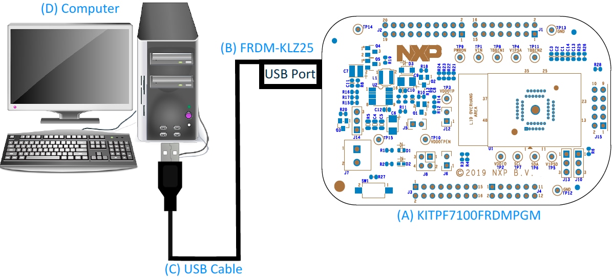
2. Plug it in
2.1 Board Description
The KITPF7100FRDMPGM is a programming board featuring a 48-pin QFN socket for PF7100 PMICs. The kit integrates all hardware needed to program the OTP registers in the PMIC.
The KITPF7100FRDMPGM integrates a communication bridge based on the FRDMKL25Z freedom board to communicate with the NXPGUI software interface to program the OTP configuration.

3. Get Software
The KITPF7100FRDMPGM can use the NXPGUI for any of the PF7100 devices. Prior to the installation of the NXPGUI software and performing device firmware updates (if needed), download and unzip the NXP_GUI_PR_version.zip file to any desired location.
Open and run the NXP_GUI_version_Setup.exe file from the unzipped package. This installs the NXPGUI software in the system. Install it in a local destination folder.
The installation package is available at PF7100 OTP Programming Board.
3.1 Updating the PF7100 NXPGUI Firmware
The FRDM-KL25Z freedom board is used to operate as a communication bridge to interface the NXPGUI with the PMIC and other I²C devices. The firmware is organized in three levels:
- At first level, the SDA uses the BOOTLOADER to operate as the main path to flash the functional code of the SDA processor. The BOOTLOADER is preprogrammed on the FRDM-KL25Z freedom boards and cannot be reflashed, to avoid permanent damage to the Freedom board
- At second level, the SDA provides a firmware loader for quick drag-and-drop update of the KL25Z MCU firmware
- At the third level, the KL25Z MCU provides the NXPGUI firmware in charge of converting the USB communication into MCU instructions to control digital I/Os, as well as I²C communication to the PMIC
If the FRDM-KL25Z is not loaded with the correct firmware to support a future software upgrade, the firmware can be updated in a few simple steps.
3.2 Flashing the FRDM-KL25Z Firmware Loader
-
This step is optional and should be performed only if the FRDM_KL25Z driver does not appear when the SDA port is
connected. Press the push button on the Freedom board and connect the USB cable into the SDA port on the Freedom
board. A new BOOTLOADER device should appear on the left pane of the file explorer

- Drag and drop the file MSD-DEBUG-FRDM-KL25Z_Pemicro_v118.SDA into the BOOTLOADER drive. File should be located in the KL25Z firmware folder
- Disconnect and reconnect the USB cable into the SDA port (this time without pressing the push button). A new device called FRDM_KL25Z is installed on the PC
3.3 Flashing the NXPGUI Firmware
If a new software or silicon release requires a firmware update on the FRDM-KL25Z freedom board, use the following steps to upgrade or downgrade the firmware of the freedom board as needed. Note that this procedure is needed only to update the firmware and may be skipped if no change is needed.
- Connect the USB cable in the SDA port (without holding the push button). The PC installs a new device called FRDM_KL25Z
- Locate the ".bin" NXPGUI driver to be installed, for example nxp-gui-fw-frdmkl25z-usb_hid-pf7100_version.bin and drag and drop the file into the FRDM_KL25Z driver
- Freedom board firmware is successfully loaded
4. Configure Hardware
4.1 Configure the Hardware for Startup
To configure the hardware and workstation, complete the following procedure:
-
Connect the KITPF7100FRDMPGM board to the top of the Freedom KL25Z board
- For standalone chip programming, introduce a PF7100 QFN device in the socket (ensure pin 1 is properly aligned)
- For inline programming, connect the interface connector to the system board and ensure that VIN power is provided either from the programmer or at the system board. Ensure that the SCL and SDA pins are connected only to the PMIC and isolated from the system bus. This configuration avoids the unpowered system from pulling the signal up or down, causing communication problems
-
Connect the USB cable from the PC to the USB port on the Freedom board
- The green LED should light up
-
The USB-HID connection will automatically search for the KITPF7100FRDMPGM, if a valid board is connected. This
is displayed by the active Start button on the top-left corner of the GUI, then click Start to
create a connection
 The Start button changes to a Stop button after it is clicked. The device status can be read from the
bottom-left corner of the NXPGUI.
The Start button changes to a Stop button after it is clicked. The device status can be read from the
bottom-left corner of the NXPGUI.

- If the board is properly recognized, press the Reset button on the Freedom board
Once the device is connected, the system is ready to perform the OTP programming.
Design Resources
Board Information
Refer to UM11482, KITPF7100FRDMPGM evaluation board user manual for additional software details.
Additional Resources
Product Summary
The product summary page for PF7100 is at 7-Channel Power Management Integrated Circuit for High Performance Applications, Fit for ASIL B Safety Level.
Tool Summary
The tool summary page for KITPF7100FRDMPGM board is at PF7100 OTP Programming Board.
The page provides overview information, technical and functional specifications, ordering information, documentation and software. The 'Get Started' guide provides quick-reference information applicable to using the KITPF7100FRDMPGM board, including the downloadable assets.
References
In addition to our PF7100: 7-Channel Power Management Integrated Circuit for High Performance Applications, Fit for ASIL B Safety Level page, you may also want to visit:
Application pages:
Hardware pages:
Software pages:
Community page: