Getting Started with the KITPF1550FRDMPGM
Contents of this document
-
Out of the Box
-
Plug It In
-
Configure Hardware
-
Get Software
Sign in to save your progress. Don't have an account? Create one.

Purchase your KITPF1550FRDMPGM
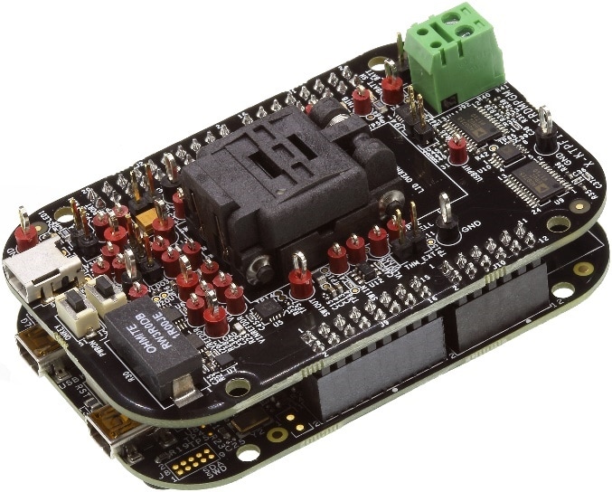
1. Out of the Box
The NXP analog product development boards provide an easy-to-use platform for evaluating NXP products. The boards support a range of analog, mixed-signal and power solutions. They incorporate monolithic integrated circuits and system-in-package devices that use proven high-volume technology. NXP products offer longer battery life, a smaller form factor, reduced component counts, lower cost, and improved performance in powering state-of-the-art systems.
This page will guide you through the process of setting up and using the KITPF1550FRDMPGM programming board.
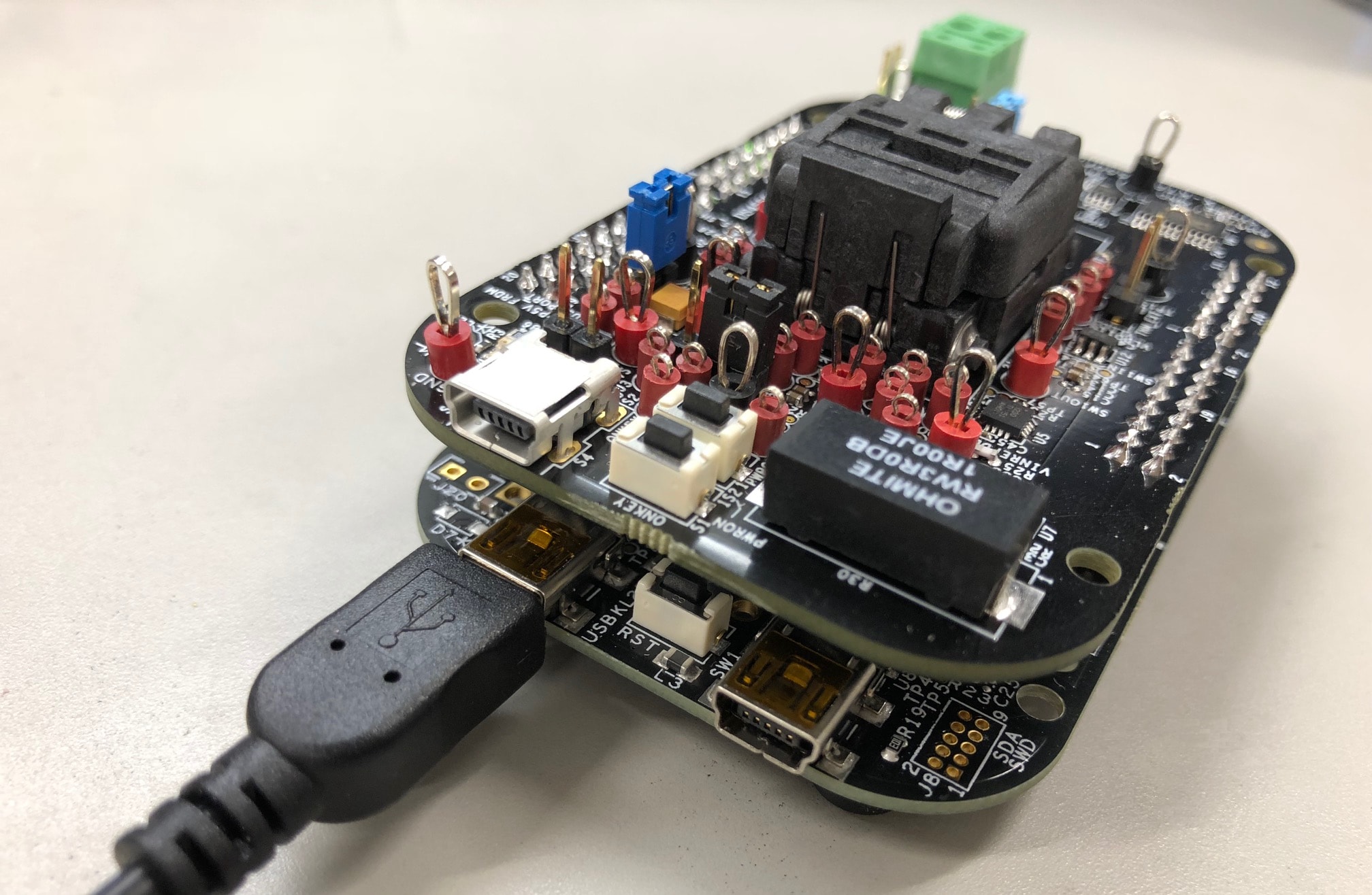
2. Plug It In
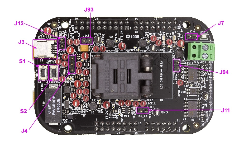
2.1 Board Features
-
Programming socket
- Clamshell 40-pin QFN socket
-
System features
- 5.0 V operating input voltage range (from USB connector)
- Integrated boost converter to supply VDDOTP programming voltage
- USB to I2C communication via the FRDM-KL25Z interface
- Inline programming interface connector
-
Attached FRDM_KL25Z
- Pre-programmed FRDM-KL25Z as a communication link between the EVB and a PC
- Easy access to MCU I/O, battery-ready, low-power operation, a standards-based form factor with expansion board options, and a built-in debug interface for flash programming and run-control
3. Configure Hardware
Suggested equipment needed for testing:
- Computer
- Mini USB type A cable
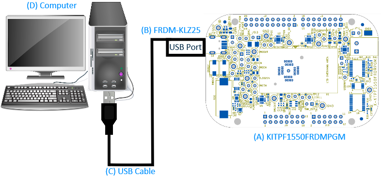
To configure the hardware, complete the following procedure:
- Plug the KITPF1550FRDMPGM board on top of the FRDM-KL25Z FRDM board
-
Connect the USB cable from the PC to the USB port on the FRDM board
- Verify that the board is receiving power (green LED is lit)
- Press Reset button on the FRDM board, to ensure that the board is properly recognized
3.1 Configure the Hardware
Suggested equipment needed for testing:
- Computer
- Mini USB type A cable
To configure the hardware, complete the following procedure:
- Plug the KITPF1550FRDMPGM board on top of the FRDM-KL25Z FRDM board
-
Connect the USB cable from the PC to the USB port on the FRDM board
- Verify that the board is receiving power (green LED is lit)
- Press Reset button on the FRDM board, to ensure that the board is properly recognized
4. Get Software
- Download KITPF1550GUI.zip from PF1550 Programming Socket Board
- Extract all the files to any desired folder on your PC and install it
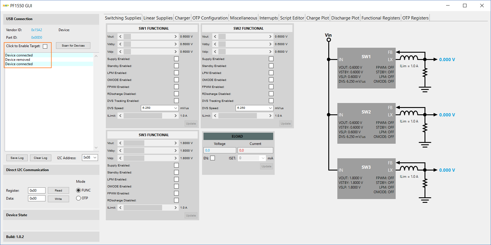
- Click PF1550 icon in the START menu to start KITPF1550GUI
4.1 OTP Programming
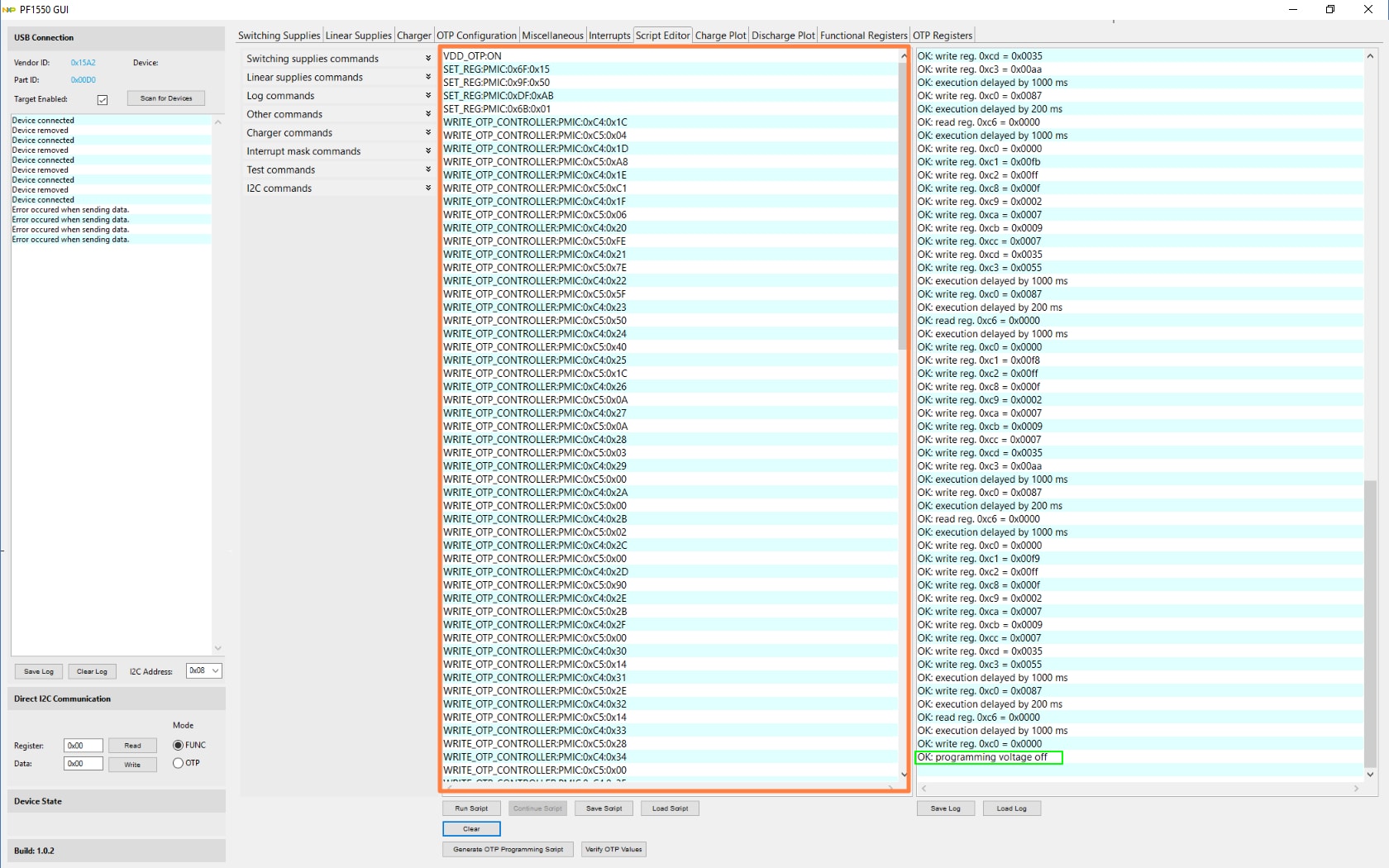
- Keep the jumper J12 connected on the KITPF1550FRDMPGM socket board
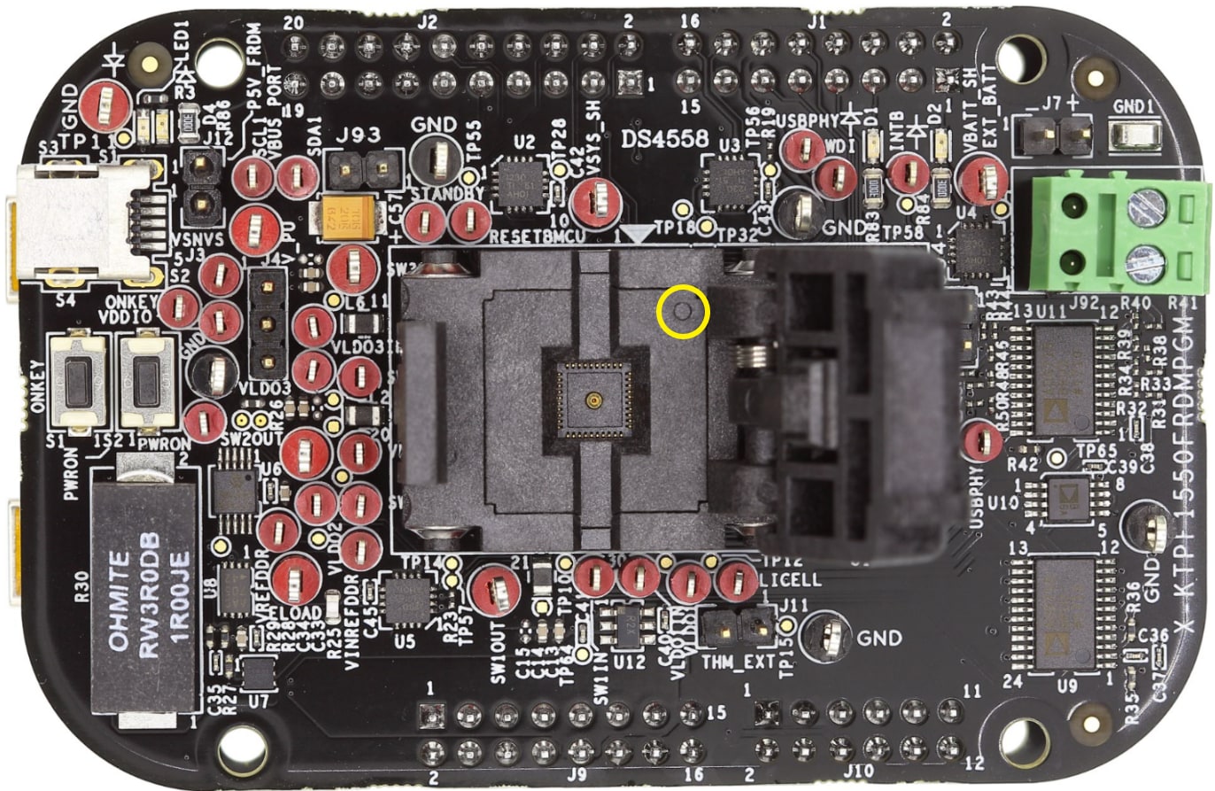
- Place a blank PF1550 part in the socket, and ensure that the chip #1 pin matches the socket marked corner
- Connect mini-USB cable between FRDM-KL25Z FRDM board and PC, then the “Device connected” prompt in KITPF1550GUI shows good connection
- Select the checkbox Click to Enable Target:
- Copy the script generated in PF1550 OTP Programming Request Form to the “Script Editor” tab in the GUI. Click Save Script to save to txt file for future loading
- Click Run Script to run the OTP programming until the following message is displayed "OK: programming voltage off”. The red LED D2 turns ON, indicating that the programming is in process
- Click Verify OTP Values to view the OTP register values of the programmed part
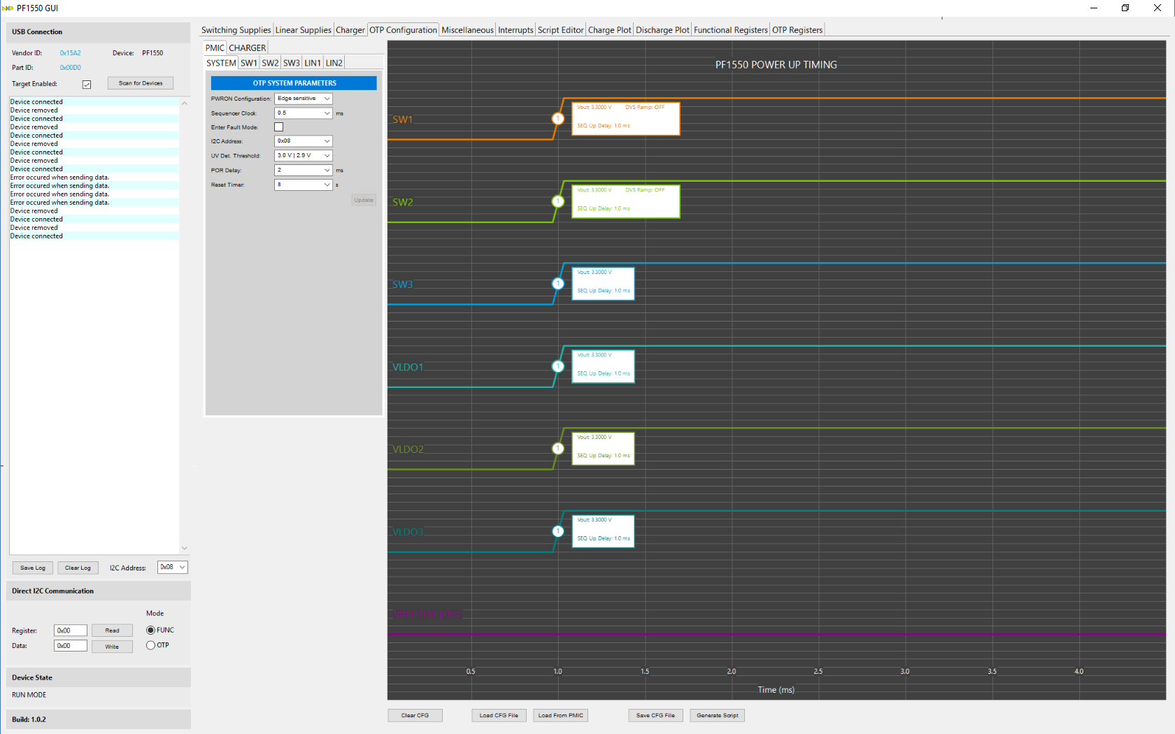
- Remove and reconnect jumper J12, then switch to “OTP Configuration” tab to view the PF1550 programmed part start-up sequence
- Unplug the mini-USB cable to continue OTP programming for the next new blank part (repeat steps 2 to 7)
Design Resources
Additional Resources
Product Summary Page
The product summary page for PF1550 is at PMIC with 1A Li+ Linear Battery Charger for Low Power Processor Systems.
Tool Summary Page
The tool summary page for KITPF1550FRDMPGM board is at PF1550 Programming Socket Board.
The page provides overview information, technical and functional specifications, ordering information, documentation, and software. The Get Started provides quick- reference information applicable to using the KITPF1550FRDMPGM board, including the downloadable assets.
References
In addition to our PF1550: PMIC with 1A Li+ linear battery charger for low-power processor systems page, you may also want to visit:
FRDM pages:
Hardware pages:
Software pages: