Getting Started with the KITPF5200FRDMEVM Evaluation Board
Contents of this document
-
Out of the Box
-
Get Hardware
-
Get Software
-
Configure Hardware
Sign in to save your progress. Don't have an account? Create one.
Purchase your PF5200 Evaluation Board
1. Out of the Box
The NXP analog product development boards provide an easy-to-use platform for evaluating NXP products. The boards support a range of analog, mixed-signal and power solutions. They incorporate monolithic integrated circuits and system-in-package devices that use proven high-volume technology. NXP products offer longer battery life, a smaller form factor, reduced component counts, lower cost and improved performance in powering state-of-the-art systems.
This page will guide you through the process of setting up and using the KITPF5200FRDMEVM board.
1.1 Kit Contents and Packing List
The KITPF5200FRDMEVM contents include:
- Assembled and tested evaluation board and preprogrammed FRDM-KL25Z microcontroller board in an anti-static bag
- 3.0 ft USB-STD A to USB-B-mini cable
- Jumpers mounted on board
- PF52 part soldered on top
- Quick Start Guide
1.2 Additional Hardware
In addition to the kit contents, the following hardware is necessary or beneficial when working with this kit.
- Power supply with a range of 3.3 V to 5.0 V. Current limit depends of the use case, but a 4.0 A current limit supports all use cases
1.3 Windows PC Workstation
This reference design requires a Windows PC workstation. Meeting these minimum specifications should produce great results when working with this evaluation board.
- USB-enabled computer with Windows 7 or Windows 10
1.4 Software
Installing software is necessary to work with this evaluation board. All listed software is available on the evaluation board's information page at KITPF5200FRDMEVM
- PF5200 NXP GUI installation package
2. Get Hardware
2.1 Board Features
- Banana 4 mm for power supply input
- Banana 4 mm for switcher 1 and switcher 2
- Selectable OTP or TBB mode
- PGOOD, RESETBMCU and XFAIL pins
- USB to I²C protocol for easy connection to software GUI
- LEDs, green and red, that indicate signal or regulator status
- LED blue to indicate that VDDOTP pin is set to 8.0 V (OTP burning voltage)
2.2 Board Description
The KITPF5200FRDMEVM kit provides an integrated platform for evaluating designs based on NXP’s PF5200 dual-channel PMIC. All PF5200 features can be accessed and monitored in a test environment.
The kit hardware consists of the KITPF5200FRDMEVM evaluation board, a FRDMKL25Z microcontroller board and the USB cable required to connect the FRDM-KL25Z to the PC.
2.3 Kit Featured Components
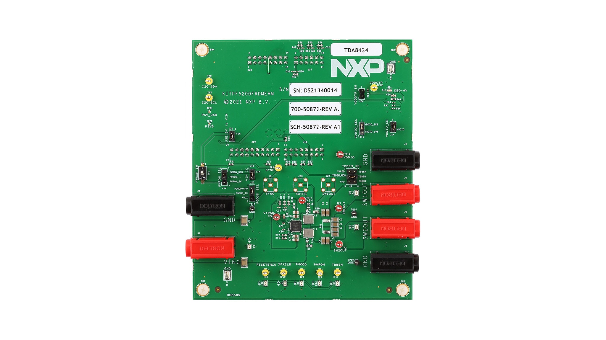
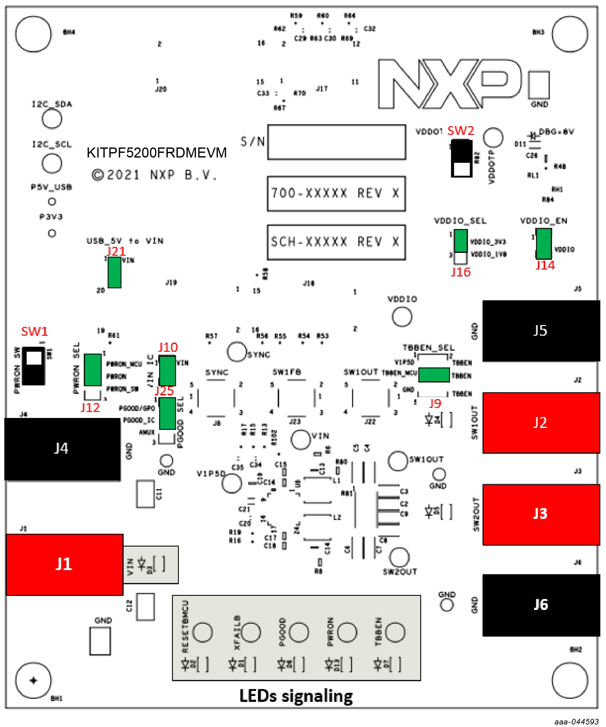
Figure 1 shows the location of key KITPF5200FRDMEVM components.
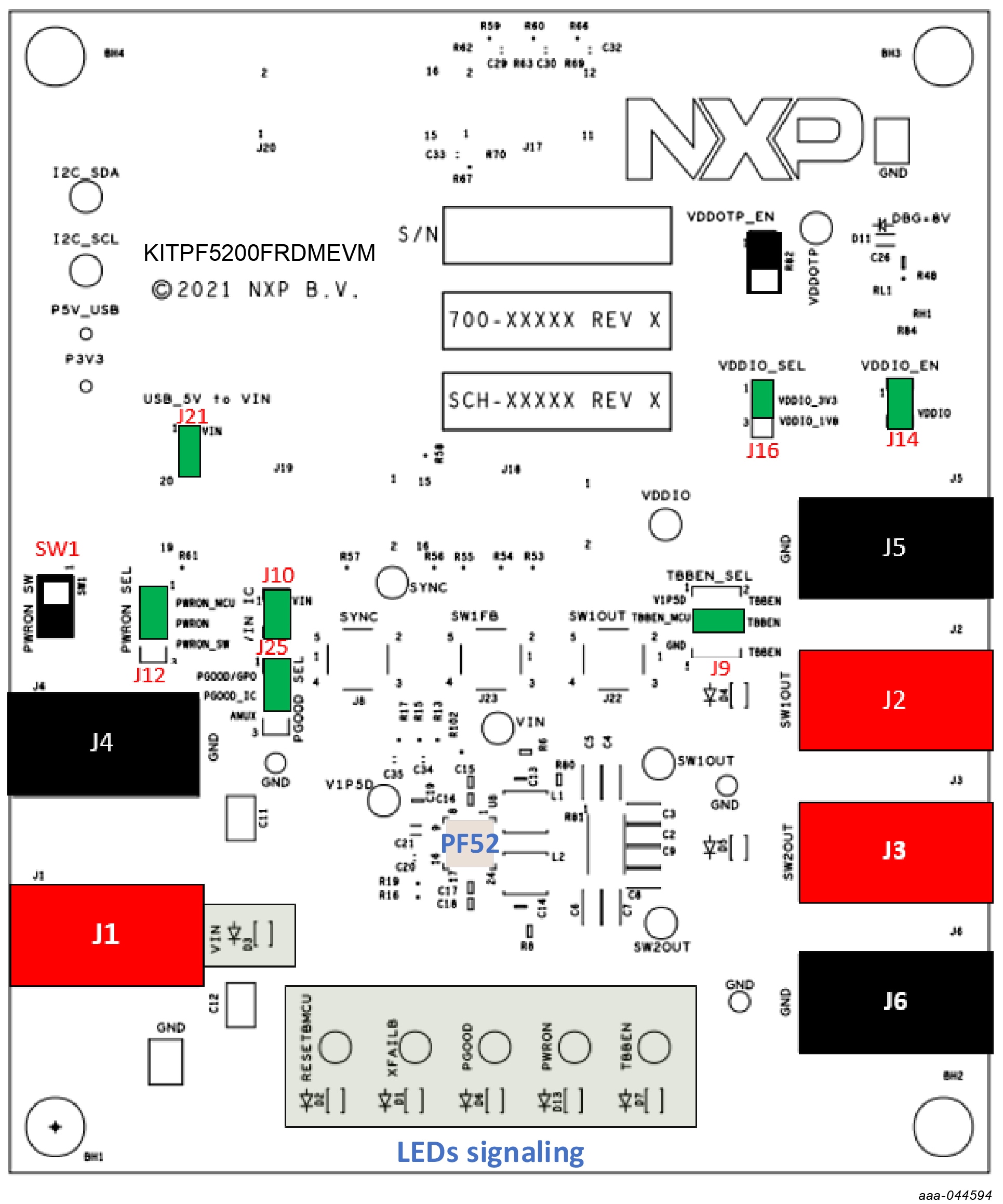
| Position | Function | Description |
|---|---|---|
J1/J4 |
VIN | Input voltage (3.3 V min / 5.5 V max) |
J1/J4 |
SW1OUT | Output for SW1 |
J3/J6 |
SW2OUT | Output for SW2 |
SW1 |
VIN switch | PWRON manual control (assume J12 on PWRON_SW position) |
J9
|
TBBEN_SEL | Apply either V1P5D or 3.3 V from MCU or GND to TBBEN pin |
J10
|
VIN_IC | Apply VIN to VIN IC pin |
J12
|
PWRON_SEL | PWRON controlled either by the MCU or manually by SW1 |
J14
|
VDDIO_EN | Apply VDDIO to VDDIO pin |
J16
|
VDDIO_SEL | VDDIO set to either 1.8 V or 3.3 V |
J22
|
PGOOD_SEL | PGOOD setting either PGGO/GPO or output of temperature junction analog voltage |

3. Get Software
The KITPF5200FRDMEVM is delivered with the GUI firmware already flashed. If your MCU firmware is already flashed, you can ignore this section. If you need to update the firmware or it is malfunctioning, follow the instructions detailed in the following sections.
3.1 Flashing the FRDM-KL25Z Firmware – Windows 7
If BOOTLOADER is already loaded on the FRDM-KL25Z board, skip Step 1 and Step 2 and start with Step 3.
-
Press the RST push-button and plug the USB cable into the SDA port on the FRDM- KL25Z board
- A new “BOOTLOADER” device appears on the left pane of the File explorer
- Locate the file MSD-DEBUG-FRDM-KL25Z_Pemicro_v118.SDA from the package and drag and drop into the BOOLTLOADER device
-
Disconnect and reconnect the USB cable into the SDA port
-
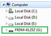
This time without pressing the RST push-button, the FRDM_KL25Z device should appear on the left pane of the File explorer as shown in the following figure
-
This time without pressing the RST push-button, the FRDM_KL25Z device should appear on the left pane of the File explorer as shown in the following figure
- Locate the file “nxp-gui-fw-frdmkl25z-usb_hid-pf5200_v0.9.bin” from the package and drag and drop the file into the FRDM_KL25Z device
- Freedom board firmware is successfully loaded. Disconnect the USB cable from the SDA port and reconnect it to the FRDM-KL25Z USB port
3.2 Flashing the FRDM-KL25Z Firmware – Windows 10
-
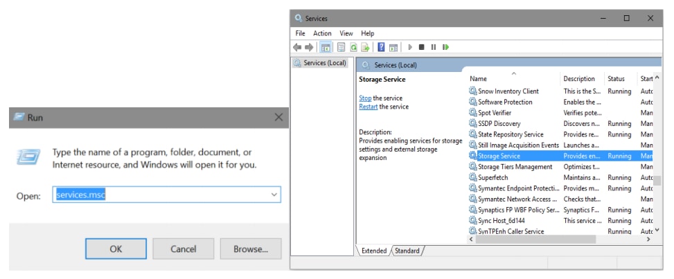
Disable the storage services: run the services, double-click on the storage service from the list and press the Stop button
If BOOTLOADER is already loaded on the FRDM-KL25Z board, skip Step 2 and Step 3 and start with Step 4
-
Press the RST push-button and plug the USB cable into the SDA port on the Freedom board
- A new “BOOTLOADER” device should appear on the left pane of the File explorer
- Drag and drop the file “MSD-DEBUG-FRDM-KL25Z_Pemicro_v118.SDA” into the BOOTLOADER drive
-
Disconnect and reconnect the USB cable into the SDA port.
- This time without pressing the RST push-button, the FRDM_KL25Z device should appear on the left pane of the File explorer as shown in the following figure
- Locate the file nxp-gui-fw-frdmkl25z-usb_hid-pf5200_v0.8.bin from the package and drag and drop the file into the FRDM_KL25Z device
- Freedom board firmware is successfully loaded. Disconnect the USB cable from the SDA port and reconnect it into the KL25Z USB port
4. Configure Hardware
4.1 Configure Hardware
The procedure for setting up the KITPF5200FRDMEVM board is as follows:
-
Make sure that the board has the jumpers configured in their default positions as shown in Figure 3. The default configuration enables the board to be fully controlled by the FRDM-KL25Z and the GUI
- Connect the power supply to
J1(VIN) andJ4(GND). The power supply should be set to an initial value of 5.0 V and current limited to 1.0 A - Verify that the FRDM-KL25Z board is firmly mounted to the KITPF5200FRDMEVM board. Also, make sure that the USB cable between the FRDM-KL25Z and the PC is securely connected. This connection is critical because the USB port not only serves as a communication channel between the PC and the FRDM-KL25Z board, but also provides voltages and references to some onboard circuits and generates the VDDIO reference for the IC
Design Resources
Additional Resources
Resources
In addition to our PF5200: Dual-Channel PMIC for Automotive Applications – 2 High Efficient LVBUCK, Fit for ASIL B Safety Level page, you may also want to visit:
- S32R45: S32R Radar MPU – High Performance for Imaging Radar
- FS8400: Safety System Basis Chip for S32 Microcontrollers, Fit for ASIL B
- NXP GUI for Automotive PMIC Families