Get Started with the FRDM-KW24D512
Contents of this document
-
Plug It In
-
Get Software
-
Build, Run
-
Create
Sign in to save your progress. Don't have an account? Create one.

Purchase your FRDM-KW24D512 | KW2xD | Wireless
1. Plug It In
Let's take your FRDM-KW24D512 for a test drive!


2. Get Software
In this step, you will be guided to download the software and tools required to build and run the connectivity solutions.
2.1 Download KW2xD Connectivity Software
Thread, IEEE 802.15.4, and SMAC Stacks
The KW2XD Connectivity Software package integrates the Kinetis Software Development Kit v2.0 and all the wireless connectivity stacks required to develop your solution using Thread, IEEE 802.15.4 and/or SMAC.
Click below to download the KW2XD Connectivity Software appropriate for your computer's operating system.
Get KW2xD Connectivity Software
For Windows
Get KW2xD Connectivity Software
For Linux
BeeStack Stack
NXP BeeStack contains features corresponding to the ZigBee Home Automation 1.2 and ZigBee Light Link 1.0 profiles. Mesh network stack layers with multi-instance support. FreeRTOS OS and NXP MQX™ RTOS configurations supported.
2.2 Install Your Toolchain
NXP offers a complimentary toolchain called Kinetis Design Studio (KDS)
No problem. The KW2XD Connectivity Software includes support for other tools such IAR.

2.3 PC Configuration
Install the CMSIS-DAP Serial drivers
The FRDM-KW24D512 has CMSIS-DAP firmware in its built-in OpenSDA debug circuit, so you’ll want to make sure that the driver for the board’s virtual COM port is installed. Before you run the driver installer, you MUST have the board plugged in to your PC.
Install the Segger J-Link drivers
If you plan on using Kinetis Design Studio, you will need to use the JLink debug interface instead of the CMSIS-DAP interface. So you will need to download and install the latest Segger J-Link drivers for your host PC to update the drivers used by Kinetis Design Studio.
Download Segger J-Link Drivers
Also, be sure to check the Kinetis Design studio installation that you plan to use when prompted to update IDE installations at the end of the driver installation. Below is an example of the prompt that you will see.
these steps to update the Jlink path variable in KDS.
2.4 Terminal Configuration
Configure your preferred terminal to 115200 baud rate, 8 data bits, no parity and 1 stop bit. To determine the port number of the FRDM-KW2XD's virtual COM port, open the device manager and look under the "Ports" group.
Not sure how to use a terminal application? Try one of these tutorials:
Tera Term Tutorial, PuTTY Tutorial3. Build, Run
These steps show how to run the SMAC Connectivity Test demo, but these steps can also be applied to any of the Wireless Connectivity demo applications.
Build the application demo
-
Open the "Connectivity_Test.eww" IAR workspace.
connectivitysoftware_install_folder \boards\frdmkw24\wireless_examples\smac\connectivity_test\freertos\iar\connectivity_test_freertos.eww/connectivitysoftware_install_folder -
Select and build the "Connectivity_Test - Debug" project by right clicking
on the project and selecting “Make”

Download and Run the application demo
-
Connect your FRDM-KW24D512 board to your PC using the mini-B USB cable and plugging into the J15 USB connector on the board.
-
Click the "Download and Debug" icon to flash the board.
-
Open a Terminal Emulator program and open a session to your FRDM-KW24D512 COM port.
Configure the terminal with these settings:
- 115200 baud rate
- No parity
- 8 data bits
- 1 stop bit
-
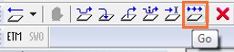
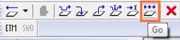
Press "Go" button.

-
The following output will be displayed in the serial terminal.
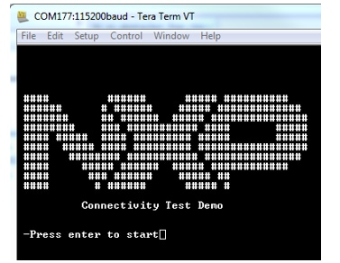
If you don’t see this output, verify your terminal settings and connections.
-
Stop the debugger by clicking on the Stop Debugging button in IAR.

-
Now unplug the first board, and plug in the other FRDM-KW24D512
-
Program the second FRDM-KW24D512 with the same SMAC firmware by using the same steps as above.
-
Close any open terminal windows, then power cycle both boards, and with both boards plugged into your computer, open up a terminal window for each board.
-
Hit the reset button each board and then hit the Enter key on the terminal to bring up the Connectivity Test options for each board.
-
Refer to
connectivitysoftware_install_folder connectivitysoftware_install_folder\docs\wireless\SMAC\Kinetis SMAC Demo Applications User's Guide.pdf document for instructions on how to run all the demo applications.
3.2 Build, Run and Debug Wireless Connectivity Examples
You probably want to build and debug a demo by yourself. Use the guide below to learn how to build and debug an example SMAC application from the Wireless Connectivity Stack in the Kinetis Design Studio (KDS) IDE or IAR Embedded Workbench IDE.
IAR Embedded Workbench IDE
These steps show how to run the SMAC Connectivity Test demo, but these steps can also be applied to any of the Wireless Connectivity demo applications.
Build the application demo
-
Open the "Connectivity_Test.eww" IAR workspace.
connectivitysoftware_install_folder \boards\frdmkw24\wireless_examples\smac\connectivity_test\freertos\iar\connectivity_test_freertos.eww/connectivitysoftware_install_folder -
Select and build the "Connectivity_Test - Debug" project by right
clicking on the project and selecting “Make”
Download and Run the application demo
-
Connect your FRDM-KW24D512 board to your PC using the mini-B USB cable and plugging into the J15 USB connector on the board.
-
Click the "Download and Debug" icon to flash the board.
-
Open a Terminal Emulator program and open a session to your FRDM-KW24D512 COM port.
Configure the terminal with these settings:
- 115200 baud rate
- No parity
- 8 data bits
- 1 stop bit
-
Press "Go" button.
-
The following output will be displayed in the serial terminal.
If you don’t see this output, verify your terminal settings and connections.
-
Stop the debugger by clicking on the Stop Debugging button in IAR.
-
Now unplug the first board, and plug in the other FRDM-KW24D512
-
Program the second FRDM-KW24D512 with the same SMAC firmware by using the same steps as above.
-
Close any open terminal windows, then power cycle both boards, and with both boards plugged into your computer, open up a terminal window for each board.
-
Hit the reset button each board and then hit the Enter key on the terminal to bring up the Connectivity Test options for each board.
-
Refer to
                connectivitysoftware_install_folder
                connectivitysoftware_install_folder
\docs\wireless\SMAC\Kinetis SMAC Demo Applications User's Guide.pdf document for instructions on how to run all the demo applications.
Kinetis Design Studio (KDS) IDE
SMAC - Kinetis Design Studio IDE
These steps show how to:
-
Load and build the demo application in Kinetis Design Studio.
Download and run the demo application.
These steps show how to run an SMAC demo, but these steps can also be applied to any of the Wireless Connectivity demo applications.
1. Load and build the application demo
-
Open Kinetis Design Studio, and set the workspace directory to an empty directory of your choice (though keep the path depth short to avoid Windows path length limitations), and click on OK.

-
Click on the "Workbench" icon to go to the main Workbench screen. This only must be done the first time a new workspace location is used.

-
Select "File->Import" from the KDS IDE menu the window that appears, expand the "General" folder and select "Existing Projects into Workspace". Then, click the "Next" button.

-
Click the "Browse" button next to the "Select root directory:" option.

-
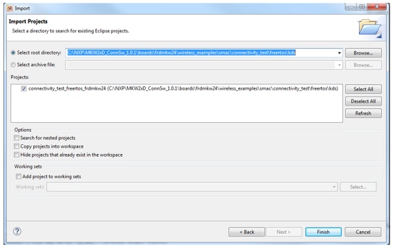
Point to the desired SMAC project. For this example, use the Connectivity Test project, which can be found at this path:
              <install_dir>\boards\frdmkw24\wireless_examples\smac
\connectivity_test\freertos\kds<install_dir> -
After pointing KDS to the correct directory, your "Import Projects" window should look like the figure below. Click the "Finish" button.
-
There are two project configurations (build targets) supported for each KSDK project:
- Debug – Compiler optimization is set to low, and debug information is generated for the executable. This target should be selected for development and debug.
- Release – Compiler optimization is set to high, and debug information is not generated. This target should be selected for final application deployment.
-
Choose the appropriate build target, "Debug" or "Release", by clicking the downward facing arrow next to the hammer icon, as shown below. For this example, select the "Debug" target.

-
The application will begin building after the build target is selected. The progress can be viewed in the Console tab at the bottom. To rebuild the application in the future, click the hammer icon (assuming the same build target is chosen).
2. Download and Run the application demo
The FRDM-KW24D512 board comes loaded with the mbed/CMSIS-DAP debug interface from the factory. This interface is not supported for the KW2x in the current version of KDS. In order to debug, you must first install either the J-Link OpenSDAv2.1 application or P&E OpenSDAv2.1 application on the board in order to use the KDS IDE to download and debug your board.
To install the JLink OpenSDAv2.1 application on the FRDM-KW24D512 board:
-
With the board unpowered, hold down the Reset button on the FRDM-KW24D512 and plug in a micro-B USB cable into the “DEBUG” USB port (J15) on the board.
Release the Reset button
-
The board will enumerate as a “BOOTLOADER” driver
-
Drag and drop the JLink OpenSDAv2.1 application .bin file for the FRDM-KW24D512 into this drive.
-
Do a power cycle, and now the board will be running the JLink OpenSDA application
-
Open a Terminal Emulator program and open a session to your FRDM-KW24D512 COM port.
Configure the terminal with these settings:
- 115200 baud rate
- No parity
- 8 data bits
- 1 stop bit
-
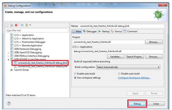
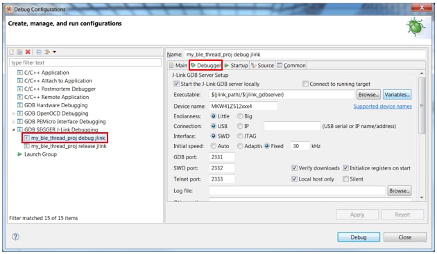
Click on the small arrow next to the green bug icon and select Debug Configurations.

-
In the Debug Configurations dialog box, select the J-Link debug configuration that corresponds to the build you are targeting: debug or release. This example focuses on the debug build.
After selecting the debugger interface, click the "Debug" button to launch the debugger.
-
If you see an error message about an unknown KW2x family, make sure you had installed the latest JLink Software and Documentation Pack first, and then restart Kinetis Design Studio and repeat the previous steps to debug again.
-
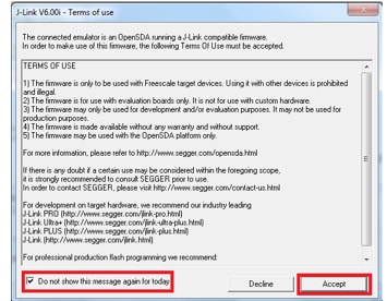
You may see a message about accepting the J-Link terms of use. Check the checkbox to disable this message for the rest of the day, and then click on Accept. Note that if you take too long, the download may fail, and you will need to try again.
-
You may also see a SWO warning which you can just click OK to dismiss:

-
Then you may also get the following message about switching to the Eclipse Debug view. Click on "Remember my decision" and then click on "Yes". This will take you to the Debug view.

-
The application is downloaded to the target and automatically runs to main():

-
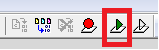
Start the application by clicking the "Resume" button:

-
The following output will be displayed in the serial terminal.
If you don’t see this output, verify your terminal settings and connections.
-
Click on the Terminate icon to stop debugging.

-
Now unplug the first board, and plug in the other FRDM-KW24D512
-
Get back to the workbench view by clicking on the C/C++ icon in the top right corner.
-
Program the second FRDM-KW24D512 with the same SMAC firmware by using the same steps as above. Close any open terminal windows, then power cycle both boards, and with both boards plugged into your computer, open up a terminal window for each board.
-
Hit the reset button each board and then hit the Enter key on the terminal to bring up the Connectivity Test options for each board.
-
Refer to <connectivitysoftware_install_folder >\docs\wireless\SMAC\Kinetis SMAC Demo Applications User's Guide.pdf document for instructions on how to run all the demo applications. <connectivitysoftware_install_folder>
After the J-Link OpenSDA app is loaded on the board:
4. Create
NXP provides a project cloner tool which allows you to copy an existing demo to use as a base for your own development, keeping the original demo app resources for reference. The cloner tool
is included in your software package download. It can be found in
4.1 Run the Project Cloner
After navigating to the Project Cloner folder, open the utility by clicking on the ProjectCloner.exe executable. Follow the directions in step two to clone a project.
4.2 Clone a Project
Follow these steps to clone a project:

-
Select a codebase path.
(Click Browse, and then in the dialog box, point the cloner to the path of the desired software installation). - Select an example to clone.
- Select a configuration (this includes, RTOS, IDE, and board)
- Enter a name for your application (if you wish to change the name from the default)
-
Select a destination folder (just as was done for selecting a codebase path).
Note: When cloning KDS projects, compile time problems can occur due to file path length issues. NXP recommends to clone your projects to "C:\NXP" to avoid compilation issues caused by lengthy file path length issues. - Select the desired IDE tools
- Click Clone Project
4.3 Open Your Project
Navigate to the
Destination root path>\boards\
4.4 Start Creating your Own Application
Modify your recently cloned application to start your own design!
For more information about the application and the APIs available, take a look at the applications development guides which can be found in \docs\wireless directory. The developer's guides for each supported wireless protocol can be found in the respective protocol folder.
Demo not working?
Did your board come in a box that looks like this?

No problem! Your board simply came in the old packaging and has a different out-of-box demo loaded into the flash memory.
You should be seeing the RGB LED toggling between each of the three colors; red, blue and green. It's OK to move onto the next step when you're ready.
Still not working?
Try proceeding to the next steps to get other example applications running on your board. If you still have problems, try contacting us through the NXP Community.
Running a demo using IAR
1. Build an Example Application
The following steps will guide you through opening the hello_world application. These steps may change slightly for other example applications as some of these applications may have additional layers of folders in their path.
-
If not already done, open the desired example application workspace. Most example application workspace files can be located using the following path:
/boards/ / / /iar Using the hello_world demo as an example, the path is:
/boards/frdmke15z/demo_apps/hello_world/iar -
Select the desired build target from the drop-down. For this example, select the “hello_world – Debug” target.

-
To build the application, click the “Make” button, highlighted in red below.
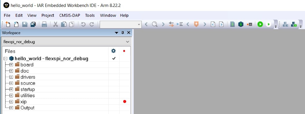
The build will complete without errors.:
2. Run an Example Application
The FRDM-KE15Z board comes loaded with the mbed/CMSIS-DAP debug interface from the factory. If you have changed the debug OpenSDA application on your board, visit http://www.nxp.com/opensda for information on updating or restoring your board to the factory state.
-
Connect the development platform to your PC via USB cable between the "SDAUSB" USB port on the board and the PC USB connector.
-
Open the terminal application on the PC (such as PuTTY or TeraTerm) and connect to the debug COM port you determined earlier. Configure the terminal with these settings:
- 15200 baud rate
- No parity
- 8 data bits
- 1 stop bit
-
Click the "Download and Debug" button to download the application to the target.

-
The application is then downloaded to the target and automatically runs to the main() function.
-
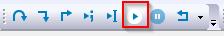
Run the code by clicking the "Go" button to start the application.

-
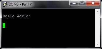
The hello_world application is now running and a banner is displayed on the terminal. If this is not the case, check your terminal settings and connections.
SMAC
These steps show how to:
-
Build the platform libraries required by the application demo
Build the demo application.
Download and run the demo application.
The example used below is for the SMAC Connectivity Test demo, but these steps can be applied to any of the Wireless Connectivity demo applications.
1. Build the platform library
-
Open the "Connectivity_Test.eww" IAR workspace.
\KW40Z_Connectivity_Software_ Connectivity_Test\usbkw40z\FreeRTOS\build\iar\Connectivity_Test.eww\ConnSw\examples\smac\ 
-
After the workspace is open, some projects are shown: One for the KSDK platform library and one for the demo application. Build ALL the required KSDK libraries by right clicking on the SDK projects and click on 'Make'.

2. Build the application demo
-
Select and build the "Connectivity_Test - Debug" project.

Note: If you select another project, don't forget to build the required KSDK libraries for that project.
3. Download and Run the application demo
Connect your USB-KW40Z board to your PC.
-
Right click on the "Connectivity_Test – Debug" project and select "Set as Active"
-
Click on "Download and Debug" icon to flash the board.

-
Open a Terminal Emulator program and open a session to your USB-KW40Z COM port.
Configure the terminal with these settings:
- 115200 baud rate
- No parity
- 8 data bits
- 1 stop bit
-
Press "Go" button.
-
The following output will be displayed in the serial terminal.

If you don't see this output, verify your terminal settings and connections.
-
Now unplug the first board, and plug in the other USB-KW40Z.
-
Program the second USB-KW40Z with the same Connectivity Test firmware by using the same steps as above.
-
Close any open terminal windows, then power cycle both boards, and with both boards plugged into your computer, open up a terminal window for each board.
-
Hit the reset button each board to bring up the Connectivity Test options for each board.
-
Refer to
\KW40Z_Connectivity_Software_ document for instructions on how to run all the demo applications.\ConnSw\doc\MKW40ZSMACDAUG.pdf – "MKW40Z Simple Media AccessController (SMAC) Demonstration Applications"
IEEE 802.15.4
These steps show how to:
-
Build the platform libraries required by the application demo.
Build the demo application.
Download and run the demo application.
The example used below is for “MyWirelessApp” application demo (Coordinator), but these steps can be applied to any of the Wireless Connectivity demo applications.
1. Build the platform library
-
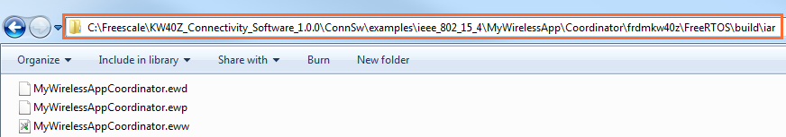
Open the "MyWirelessAppCoordinator.eww" IAR workspace.
\KW40Z_Connectivity_Software_ \ConnSw\examples \ieee_802_15_4\MyWirelessApp\Coordinator\usbkw40z\FreeRTOS\build\iar\MyWirelessAppCoordinator.eww
-
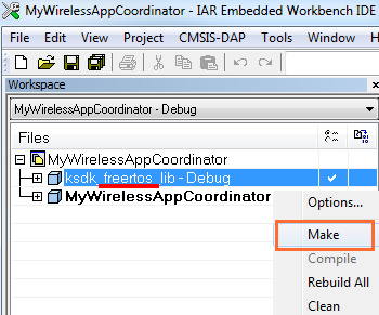
After the workspace is open, some projects are shown: One for the KSDK platform library and one for the demo application. Build ALL the required KSDK libraries by right clicking on the SDK projects and click on 'Make'.
2. Build the application demo
-
Select and build the "MyWirelessAppCoordinator - Debug" project.
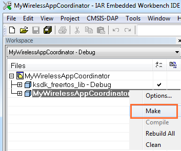
Note: If you select another project, don’t forget to build the required KSDK libraries for that project.
3. Download and Run the application demo
Connect your USB-KW40Z board to your PC.
-
Right click on the "MyWirelessAppCoordinator – Debug" project and select "Set as Active"
-
Click on "Download and Debug" icon to flash the board.

-
Open a Terminal Emulator program and open a session to your USB-KW40Z COM port.
Configure the terminal with these settings:
- 115200 baud rate
- No parity
- 8 data bits
- 1 stop bit
-
Press "Go" button.
-
The following output will be displayed in the serial terminal.

If you don't see this output, verify your terminal settings and connections.
-
Now unplug the first board, and plug in the other USB-KW40Z.
-
Program the second USB-KW40Z with the "MyWirelessApp" End Device demo application which can be found at
\KW40Z_Connectivity_Software_ \ConnSw\examples\ieee_802_15_4\MyWirelessApp\EndDevice\usbkw40z\FreeRTOS\build\iar\MyWirelessAppEndDevice.eww using the same steps as above. -
Close any open terminal windows, then power cycle both boards, and with both boards plugged into your computer, open up a terminal window for each board.
-
Press SW1 on the Coordinator board, and then press SW1 on the board programmed with the EndDevice application, and wait for them to connect.
-
Once connected, type into the terminal of either of the boards, and you will see the text print out on the other board.
-
Refer to
\KW40Z_Connectivity_Software_ document for instructions on how to run all the demo applications.\ConnSw\doc\802154MPDAUG.pdf – "NXP 802.15.4 Media Access Controller (MAC) Demo Applications"
Running a demo using Kinetis Design Studio IDE
1. Install KDS Updates
Before using KDS IDE with KSDK, it is recommended that you make sure that your tools are up-to-date. The steps discussed below are shown using the Windows version of KDS, but are identical for Mac and Linux users.
-
Select "Help" -> "Check for Updates".

-
Install all updates from Freescale/NXP – these are denoted by “com.NXP.xxx” or “com.nxp.xxx”. There may also be updates for things such as toolchain or debug interfaces. While these additional updates are typically OK to install, sometimes they may cause issues since they aren’t released as part of the KDS toolchain.
2. Build an Example Application
The following steps will guide you through opening the hello_world application. These steps may change slightly for other example applications as some of these applications may have additional layers of folders in their path.
NOTE
The steps required for Linux and Mac OS are identical to those for Windows.
-
Select File->Import from the KDS IDE menu. In the window that appears, expand the "Project of Projects" folder and select "Existing Project Sets". Then, click the "Next" button.

-
Click the "Browse" button next to the "Import from file:" option.

-
Point to the example application project, which can be found using this path:
/boards/ / / /kds For this guide, choose the specific location:
/boards/frdmke15z/demo_apps/hello_world/kds -
After pointing to the correct directory, your "Import Working Sets and Projects" window should look like the figure below. Click the "Finish" button.

-
There are two project configurations (build targets) supported for each KSDK project:
- Debug – Compiler optimization is set to low, and debug information is generated for the executable. This target should be selected for development and debug.
- Release – Compiler optimization is set to high, and debug information is not generated. This target should be selected for final application deployment.
-
Choose the appropriate build target, "Debug" or "Release", by clicking the downward facing arrow next to the hammer icon, as shown below. For this example, select the "Debug" target.

-
The library starts building after the build target is selected. To rebuild the library in the future, click the hammer icon (assuming the same build target is chosen).
3. Run an Example Application
The FRDM-KE15Z board comes loaded with the mbed/CMSIS-DAP debug interface from the factory. If you have changed the debug OpenSDA application on your board, visit http://www.nxp.com/opensda for information on updating or restoring your board to the factory state.
NOTE
Mac users must install the J-Link OpenSDA application in order to use the KDS IDE to download and debug their board.
-
Connect the development platform to your PC via USB cable between the "SDAUSB" USB port on the board and the PC USB connector.
-
Open the terminal application on the PC (such as PuTTY or TeraTerm) and connect to the debug COM port you determined earlier. Configure the terminal with these settings:
- 15200 baud rate
- No parity
- 8 data bits
- 1 stop bit
-
For Linux OS users only, run the following commands in your terminal. These install libudev onto your system, which is required by KDS IDE to launch the debugger.
user@ubuntu:~$ sudo apt-get install libudev-dev libudev1user@ubuntu:~$ sudo ln –s /usr/lib/x86_64-linux-gnu/libudev.so /usr/lib/x86_64-linux-gnu/libudev.so.0 -
Ensure that the debugger configuration is correct for the target you're attempting to connect to. This refers to the OpenSDA interface of your board. If you’re unsure what your board has, please consult Appendix B of the PDF linked in the top right hand corner of this dialog.
-
To check the available debugger configurations, click the small downward arrow next to the green "Debug" button and select "Debug Configurations".

-
In the Debug Configurations dialog box, select debug configuration that corresponds to the hardware platform you’re using. For Windows or Linux users, select is the mbed/CMSIS-DAP option under OpenOCD For Mac users, select J-Link.
After selecting the debugger interface, click the "Debug" button to launch the debugger.

-
-
The application is downloaded to the target and automatically run to main():

-
Start the application by clicking the "Resume" button:

-
The hello_world application is now running and a banner is displayed on the terminal. If this is not the case, check your terminal settings and connections.

Running a demo using Arm
1. Set Up Toolchain
This section contains the steps to install the necessary components required to build and run a KSDK demo application with the Arm GCC toolchain, as supported by the Kinetis SDK. There are many ways to use Arm GCC tools, but this example focuses on a Windows environment. Though not discussed here, GCC tools can also be used with both Linux OS and Mac OSX.
Install GCC Arm Embedded Toolchain
Download and run the installer from launchpad.net/gcc-arm-embedded. This is the actual toolchain (i.e., compiler, linker, etc.). The GCC toolchain should correspond to the latest supported version, as described in the Kinetis SDK Release Notes.
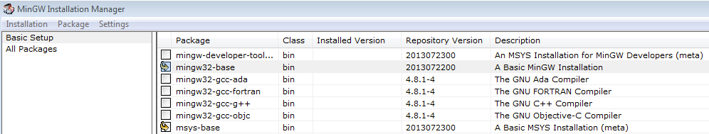
Install MinGW
The Minimalist GNU for Windows (MinGW) development tools provide a set of tools that are not dependent on third party C-Runtime DLLs (such as Cygwin). The build environment used by the KSDK does not utilize the MinGW build tools, but does leverage the base install of both MinGW and MSYS. MSYS provides a basic shell with a Unix-like interface and tools.
-
Download the latest MinGW mingw-get-setup installer from sourceforge.net/projects/mingw/files/Installer/.
-
Run the installer. The recommended installation path is C:\MinGW, however, you may install to any location.
-
Ensure that the "mingw32-base" and "msys-base" are selected under Basic Setup.
-
Click "Apply Changes" in the "Installation" menu and follow the remaining instructions to complete the installation.
-
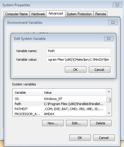
Add the appropriate item to the Windows operating system Path environment variable. It can be found under Control Panel -> System and Security -> System -> Advanced System Settings in the "Environment Variables..." section. The path is:
\bin Assuming the default installation path, C:\MinGW, an example is shown below. If the path is not set correctly, the toolchain does not work.
NOTE
If you have "C:\MinGW\msys\x.x\bin" in your PATH variable (as required by KSDK 1.0.0), remove it to ensure that the new GCC build system works correctly.
-
Download CMake 3.0.x from www.cmake.org/cmake/resources/software.html.
-
Install CMake, ensuring that the option "Add CMake to system PATH" is selected when installing. It's up to the user to select whether it's installed into the PATH for all users or just the current user. In this example, the assumption is that it's installed for all users.

-
Follow the remaining instructions of the installer.
-
You may need to reboot your system for the PATH changes to take effect.
NOTE
The installation path cannot contain any spaces.
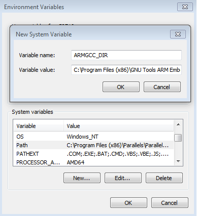
Add a New Environment Variable for ARMGCC_DIR
Create a new system environment variable and name it ARMGCC_DIR. The value of this variable should point to the Arm GCC Embedded tool chain installation path, which, for this example, is:
C:\Program Files (x86)\GNU Tools Arm Embedded\4.9 2015q3
Reference the installation folder of the GNU Arm GCC Embedded tools for the exact path name of your installation.
Install CMake
2. Build an Example Application
To build an example application, follow these steps.
-
1. If not already running, open a GCC Arm Embedded tool chain command window. To launch the window, from the Windows operating system Start menu, go to “Programs -> GNU Tools Arm Embedded
” and select “GCC Command Prompt”. 
-
Change the directory to the example application project directory, which has a path like this:
/boards/ / / /armgcc For this guide, the exact path is:
/boards/frdmke15z/demo_apps/hello_world/armgcc -
Type “build_debug.bat” on the command line or double click on the "build_debug.bat" file in Windows operating system Explorer to perform the build. The output is shown in this figure:

3. Run an Example Application
The GCC tools require a J-Link debug interface. To update the OpenSDA firmware on your board to the latest J-Link app, visit www.nxp.com/opensda. After installing the J-Link OpenSDA application, download the J-Link driver and software package from www.segger.com/downloads.html.
-
Connect the development platform to your PC via USB cable between the "SDAUSB" USB port on the board and the PC USB connector.
-
Open the terminal application on the PC (such as PuTTY or TeraTerm) and connect to the debug COM port you determined earlier. Configure the terminal with these settings:
- 15200 baud rate
- No parity
- 8 data bits
- 1 stop bit
-
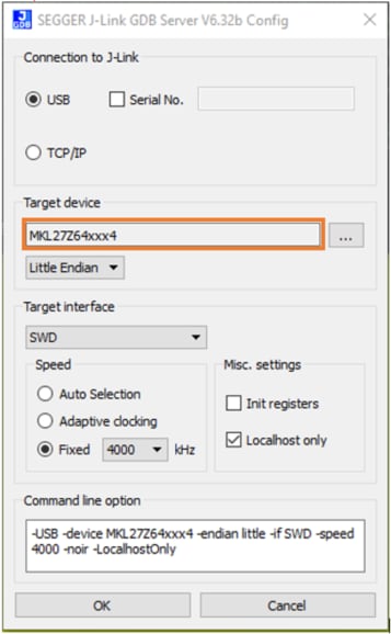
Open the J-Link GDB Server application. Assuming the J-Link software is installed, the application can be launched by going to the Windows operating system Start menu and selecting "Programs -> SEGGER -> J-Link
J-Link GDB Server". -
Modify the settings as shown below. The target device selection chosen for this example is the “MK64FN1M0xxx12” and use the SWD interface.

-
After it is connected, the screen should resemble this figure:

-
If not already running, open a GCC Arm Embedded tool chain command window. To launch the window, from the Windows operating system Start menu, go to "Programs -> GNU Tools Arm Embedded
" and select "GCC Command Prompt". 
-
Change to the directory that contains the demo application output. The output can be found in using one of these paths, depending on the build target selected:
/boards/ / / /armgcc/debug /boards/ / / /armgcc/release For this guide, the path is:
/boards/frdmke15z/demo_apps/hello_world/armgcc/debug -
Run the command "arm-none-eabi-gdb.exe
.elf". For this example, it is "arm-none-eabi-gdb.exe hello_world.elf". 
-
Run these commands:
- "target remote localhost:2331"
- "monitor reset"
- "monitor halt"
- "load"
- "monitor reset"
-
The application is now downloaded and halted at the reset vector. Execute the "monitor go" command to start the example application.
The hello_world application is now running and a banner is displayed in the terminal window.

Projects and Tutorials
Tera Term Tutorial
Tera Term is a very popular open source terminal emulation application. This program can be used to display information sent from your NXP development platform's virtual serial port.
- Download Tera Term from SourceForge. After the download, run the installer and then return to this webpage to continue.
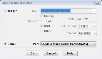
- Launch Tera Term. The first time it launches, it will show you the following dialog. Select the serial option. Assuming your board is plugged in, there should be a COM port automatically populated in the list.
- Configure the serial port settings (using the COM port number identified earlier) to 115200 baud rate, 8 data bits, no parity and 1 stop bit. To do this, go to Setup -> Serial Port and change the settings.
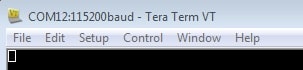
- Verify that the connection is open. If connected, Tera Term will show something like below in it's title bar.
- You're ready to go
Putty Tutorial
PuTTY is a popular terminal emulation application. This program can be used to display information sent from your NXP development platform's virtual serial port.
- Download PuTTY using the button below. After the download, run the installer and then return to this webpage to continue.
- Launch PuTTY by either double clicking on the *.exe file you downloaded or from the Start menu, depending on the type of download you selected.
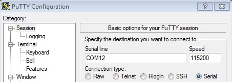
- Configure In the window that launches, select the Serial radio button and enter the COM port number that you determined earlier. Also enter the baud rate, in this case 115200.
- Click Open to open the serial connection. Assuming the board is connected and you entered the correct COM port, the terminal window will open. If the configuration is not correct, PuTTY will alert you.
- You're ready to go
Update jlink_path Tutorial
-
Click the small arrow next to the green bug icon.

-
Select Debug Configurations.

-
Select a project under the GDB Segger J-Link Debugging category, and then select the Debugger tab.
-
Then select “Variables…” next to the Executable box.

-
In the next dialog box, find the jlink_path variable, select it, and then select Edit Variables...

-
The Preferences dialog box will open. Select the jlink_path variable and then select Edit.

-
In the Edit Variable: jlink_path dialog box, ensure the path and description are as shown below.

-
Be sure to click “OK” when closing all dialog boxes.