Getting Started with the SJA1110-EVM
Contents of this document
-
Out of the Box
-
Get Hardware
-
Configure Hardware
-
Get Software
Sign in to save your progress. Don't have an account? Create one.

Purchase your SJA1110-EVM
1. Out of the Box
The NXP® analog product development boards provide an easy-to-use platform for evaluating NXP products.
The SJA1110-EVM is an evaluation board for the SJA1110 automotive Ethernet switch. The board includes two SJA1110A switches and it enables the evaluation of all supported features including AVB, TSN and the control of two switches in cascaded configuration. It is compatible the SJA1110 software development kit (SDK) and the optional AVB/gPTP middleware (available separately).
The board offers 13x 100BASE-T1 PHYs, all compatible with OPEN Alliance TC10 wake-up Forwarding. It also offers 1x 100BASE-TX and 1x 1000BASE-T PHYs with RJ45 connector, as well as three generic SFP and SFP+ connectors for external multi-gig PHYs.
The SJA1110-EVM board supports the SABRE connector capable of mating with NXP processor and controller motherboards such as i.MX and S32x processors families.
This page guides you through setting up and using the SJA1110-EVM evaluation board.
1.1 Kit Contents and Packing List
The SJA1110-EVM contents include:
- Assembled and tested SJA1110-EVM in an anti-static bag
- Subscription card
1.2 Additional Hardware
In addition to the kit contents, the following hardware is necessary or beneficial when working with this kit.
-
Micro USB cable
- Needed for Python tools
- Needed for SDK when using OpenSDA (instead of another debugger; for a list of supported debuggers, see SJA1110 SDK documentation)
- Small screw driver (1.8 mm) for the screw sockets of the T1 ports
-
SFP (for connecting to the SFP receptacles):
- 1000Base-T SFP Copper
Rj4510Gtek ASF-GE2-T - Aquantia AQS-109-B0C2-CB
- AXCEN AXGT-R1T4-05I3
- 1000Base-T SFP Copper
-
SGMII DAC cable (for connecting to the SFP receptacles):
- MikroTik SFP+ 1m S+DA0001
1.3 Software
Depending on the use case for this board, installing software is necessary.
- SDK for configuration of the switch and programming of internal microcontroller
- Python configuration and host tools for switch configuration
- Linux® driver for configuration of the switch using external microcontroller
- gPTP example software upon request (optional)
2. Get Hardware
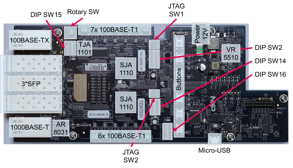
2.1 Board Description
The SJA1110-EVM board allows both entry into the world of the NXP® automotive switch and evaluation of the SJA1110 chip in different use cases and configurations.
The board is not intended for doing all PMA tests for the built-in PHYs. The relevant signals are not brought out to SMA connectors, which are essential for proper measurements.
2.2 Board Features
- Two cascaded SJA1110A switch devices
- Power supply based on VR5510 PMIC using a single 12 volt input
-
Various Ethernet ports:
- 12x 100BASE-T1 ports (SJA1110A internal PHYs)
- 1x 100BASE-T1 port using TJA1101 PHY
- 1x Gigabit Ethernet port using AR8031 PHY
- 1x 100BASE-TX port (SJA1110A internal PHY)
- Two SFP receptacles
- One SFP+ receptacle
- Debug header
- Multiple DIP switches to select between board operation modes and change specific settings
- Several push buttons (with hardwired or
SWdefined function) - USB connector for SPI access and OpenSDA
- JTAG as debugging connector for the ARM cores
- SABRE connector to easy connect to NXP processor and controller mother-cards such as i.MX6, i.MX8, S32K1, S32K3, S32GV and S32G
- Several LEDs controlled by hardware or software
3. Configure Hardware
There are two possible scenarios to deploy an example design to the SJA1110-EVM board: using the S32 Design Studio or using the Python SJA1110-EVM host tools package.
3.1 Use SDK
To run the example, you need the following:
- One SJA1110-EVM board
- One power adapter 12 V
- One personal computer
-
One supported debugger, such as:
- Lauterbach base probe with Arm® Cortex® debug probe
- Lauterbach uTrace for Cortex-M
- Multilink Universal RevC/D, or
- Multilink Universal FX RevB/C

To configure the hardware, do the following:
- Install the SDK with SJA1110 support
- Unpack the board. Set the jumper (
J58connected) and the DIP switches: -
Connect PC to SJA1110-EVM:
- a. Connect supported debugger to “JTAG
SW1”
- a. Connect supported debugger to “JTAG
- Connect the power supply to the barrel connector and power up the board. All power LEDs should light up
- Open SDK
-
Import Example Design:
- a. Click New S32DS Project from Example
- b. Select
switch_config_sja1110evm, and then click Finish
-
Optional: Open configuration views:
- a. Click Open S32 Configuration
- b. Click → Peripherals to view and adapt the switch-related configuration
-
Build the project:
- a. Select the configuration to be built RAM (Debug_RAM) by left-clicking the downward arrow corresponding to the build button
- b. Wait for the build action to be completed before continuing to the next step
-
Run the project:
- a. Go to Run and select Debug Configurations. Four debug configurations are displayed for this project
- b. Select the desired debug configuration and click Launch. The perspective changes to the Debug Perspective
- c. Use the controls to control the program flow
- d. The switch/board is now working according to example design

3.2 Use the Python Host Tools Package
To run the example, you need the following:
- One SJA1110-EVM board
- One power adapter 12 V
- One personal computer
- One USB cable

To configure the hardware, perform the following steps:
- Install Python Host Tools Package and needed drivers
- Unpack the board. Set the Jumper (
J58connected) and the DIP switches: - Connect PC to SJA1110-EVM:
Make sure that there is no other FTDI device connected to the PC, and the PC has been powered up when connecting the board.
Connect the SJA1110-EVM to the PC with a MicroUSB cable plugged into Micro USB connector - Connect the power supply to the barrel connector and power up the board.
All power LEDs should light up -
Start the Python script
read_deviceid.pyfrom the SJA1110-EVM subfolder. The script reads out the device ID of both switches and therefore can be used to verify if the switches can be reached. The following message is displayed: This confirms that the software installation and the board setup are accurate
- Start the Python script
setup_sja1110evm_simple.py.This script initializes both switches and loads a very simple static configuration into both switches - Connect ethernet nodes to the ports, and start sending and receiving traffic
4. Get Software
4.1 Install S32 Design Studio for ARM + SDK
-
Download and install S32 Design Studio S32DS3.4 for ARM
- Log in to NXP
- Search: “S32DS 3.4” (SJA1110SDK supported by this version v3.4.0)
- The license key for SDK activation is included in the box
-
Download and install SDK
- Download SJA1110SDK file (SJA1110 SDK RTM 1.0 or newer)
- Open S32 Design Studio and click Help → Update Software
- Select From Archive and browse to SDK-zip-file
- Accept license and install
Design Resources
Product Summary Page
The product summary page for SJA1110 is at SJA1110.
Tool Summary Page
The tool summary page for SJA110-EVM board is at SJA1110-EVM.
The page provides overview information, technical and functional specifications, ordering information, documentation and software. The Get Started provides quick-reference information applicable to using the SJA1110-EVM board, including the downloadable assets.
Additional References
Product pages:
- SJA1105PEL/QEL/REL/SEL Series Ethernet Switches
- S32G processors for Vehicle Networking
- VR5510: Multi-Channel (9) PMIC for S32G Processor - 8 High Power, 1 Low Power, fit for ASIL D Safety level
- MPC574xB-C-G: Ultra-Reliable MCUs for Automotive and Industrial Control and Gateway