Getting Started with the SC18IS604-EVB Evaluation Board
Contents of this document
-
Out of the Box
-
Get Hardware
-
Configure Hardware
Sign in to save your progress. Don't have an account? Create one.

Purchase your SC18IS604-EVB: SPI to I²C Bridge Evaluation Board
1. Out of the Box
The NXP analog product development boards provide an easy-to-use platform for evaluating NXP products. The boards support a range of analog, mixed-signal and power solutions. They incorporate monolithic integrated circuits and system-in-package devices that use proven high-volume technology. NXP products offer longer battery life, a smaller form factor, reduced component counts, lower cost and improved performance in powering state-of-the-art systems.
This page will guide you through the process of setting up and using the SC18IS604-EVB evaluation board.
2. Get Hardware
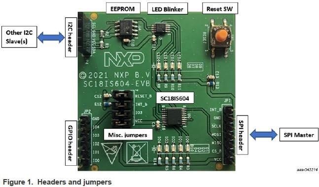
2.1 Board Features
- 7-pin 100 mil spacing SPI interface header (
JP1) - On-board I²C EEPROM and LED blinker which can be directly accessed by the external SPI controller via the SC18IS604
-
4-pin 100 mil spacing I²C interface header (
JP4) to allow other I²C devices to be connected to the evaluation board to be accessed via the SC18IS604
2.2 Board Description
The SC18IS604-EVB board is designed to be connected to an external SPI controller via a 7-pin male (JP1) header. The SC18IS604-EVB evaluation board has an on-board
I²C target serial EEPROM and an I²C target LED blinker, which can be directly accessed by the external SPI controller via SC18IS604. The external SPI
controller can write, read and program the serial EEPROM/LED blinker without requiring an I²C target to be connected to the board.
The 3V3 power for the evaluation board should be supplied via this I²C interface header as well.
The SC18IS604-EVB evaluation board also has an I²C interface header (JP4) to allow other I²C target devices to be connected to the
SC18IS604-EVB evaluation board. These I²C target devices can be accessed directly by the SPI controller via the SC18IS604 SPI to I²C bridge.
3. Configure Hardware
3.1 Configure the Hardware
- Connect 3.3 V to
JP1pin 5 - Connect external SPI controller to
JP1pin 6 (CS), pin 5 (MISO), pin 4 (MOSI), pin 3 (SCLK) - Connect ground to
JP1pin 2 - If interrupt is supported, connect interrupt signal to
JP1pin 1 - SC18IS604 is reset up on POR but can be reset externally via the on-board switch
SW1 - The board is powered and SC18IS604 can be accessed by the SPI controller
Design Resources
Additional Information
In addition to our SC18IS604: SPI to I²C-Bus Bridge page, you may also want to visit:
- UART Pages: SC16IS752_SC16IS762, SC16IS741
- Hardware Pages: Analog Toolbox