Getting Started with the S32K388EVB-Q289 Evaluation Board for General Purpose
Contents of this document
-
Out of the Box
-
Get Software
-
Plug It In
Sign in to save your progress. Don't have an account? Create one.
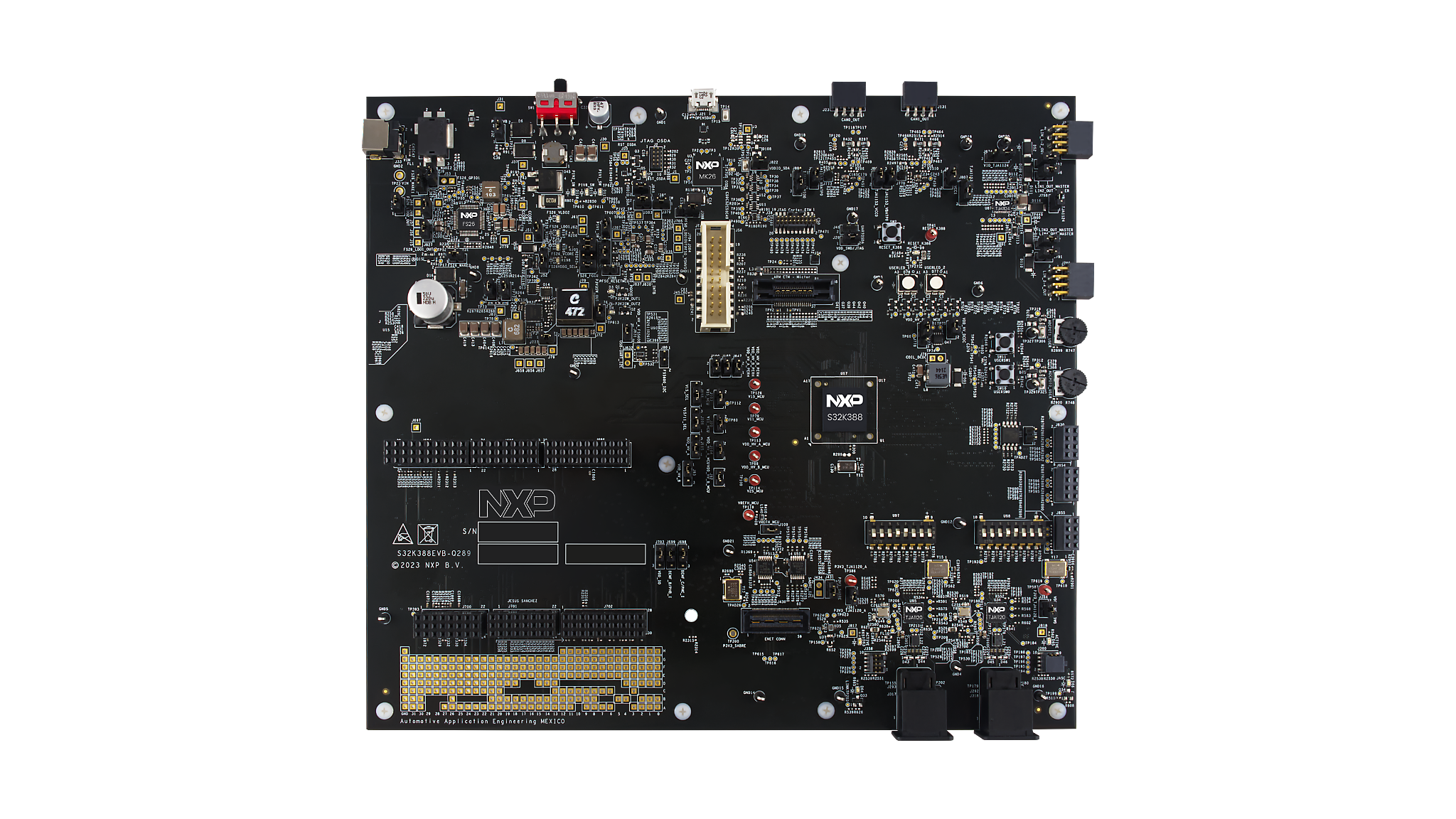
Purchase your S32K388EVB-Q289 Evaluation Board for Automotive General Purpose

2. Get Software
2.1 Get the Integrated Development Environment (IDE)
Download and install S32 Design Studio IDE for S32 Platform.
2.2 Install the S32K3xx Development Package and RTD
Go to Help → S32DS Extensions and Updates from the top menu to open the S32DS Extensions and Updates. Install S32K3xx Development Package.

Continue with the installation of Real Time Drivers for S32K3xx.

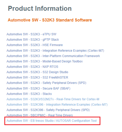
2.3 Download and Install Elektrobit tresos Studio and Real-Time Drivers (Only AUTOSAR Users)
Download and install Elektrobit Tresos Studio / AUTOSAR Configuration Tool from S32K3 Standard Software Package.
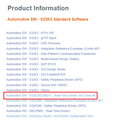
Download and install the .exe file of the S32K3 Real-Time Drivers for Cortex-M from the S32K3 Standard Software Package.
The installer will ask for the EB tresos installation directory on your disk, saving time in configuration.
Note: You will receive an activation code via email. If you installed RTD prior to EB tresos, create a SW32K3_RTD_4.4_x.y.z.link file in: C:\EB\tresos\links folder with the content: ""path=C:/NXP/SW32K3_RTD_R21-11_x.y.z"", where x,y,z refers to installed RTD version. 
2.4 Get the Run-Time Debugging Tool
S32K3X8EVB-Q289 performs better when using the FreeMASTER Run-Time Debugging Tool.
The FreeMASTER communication driver for S32K3 microcontrollers is also needed; The FreeMASTER communication driver for S32K3 microcontrollers is also needed; download it from the Automotive SW - S32K3 - S32 FreeMASTER link in the S32K3 Standard Software Package.
Open the S32DS Extensions and Updates dialog (menu → Help → S32DS Extensions and Updates), click pn Add Update Sites link and navigate to the FreeMASTER communication driver for S32K3 (zip file starting with "com.") on your disk.
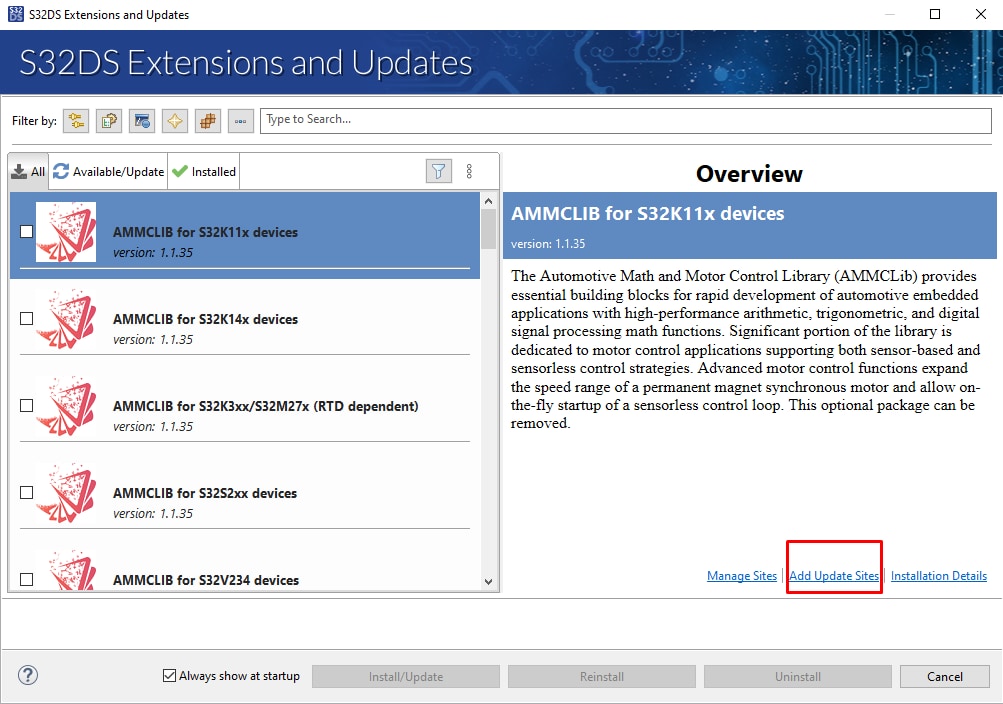
Install FreeMASTER Communication driver for S32K3.

Aditional optional software may be downloaded from S32K3 Reference Software Package.
3. Plug It In
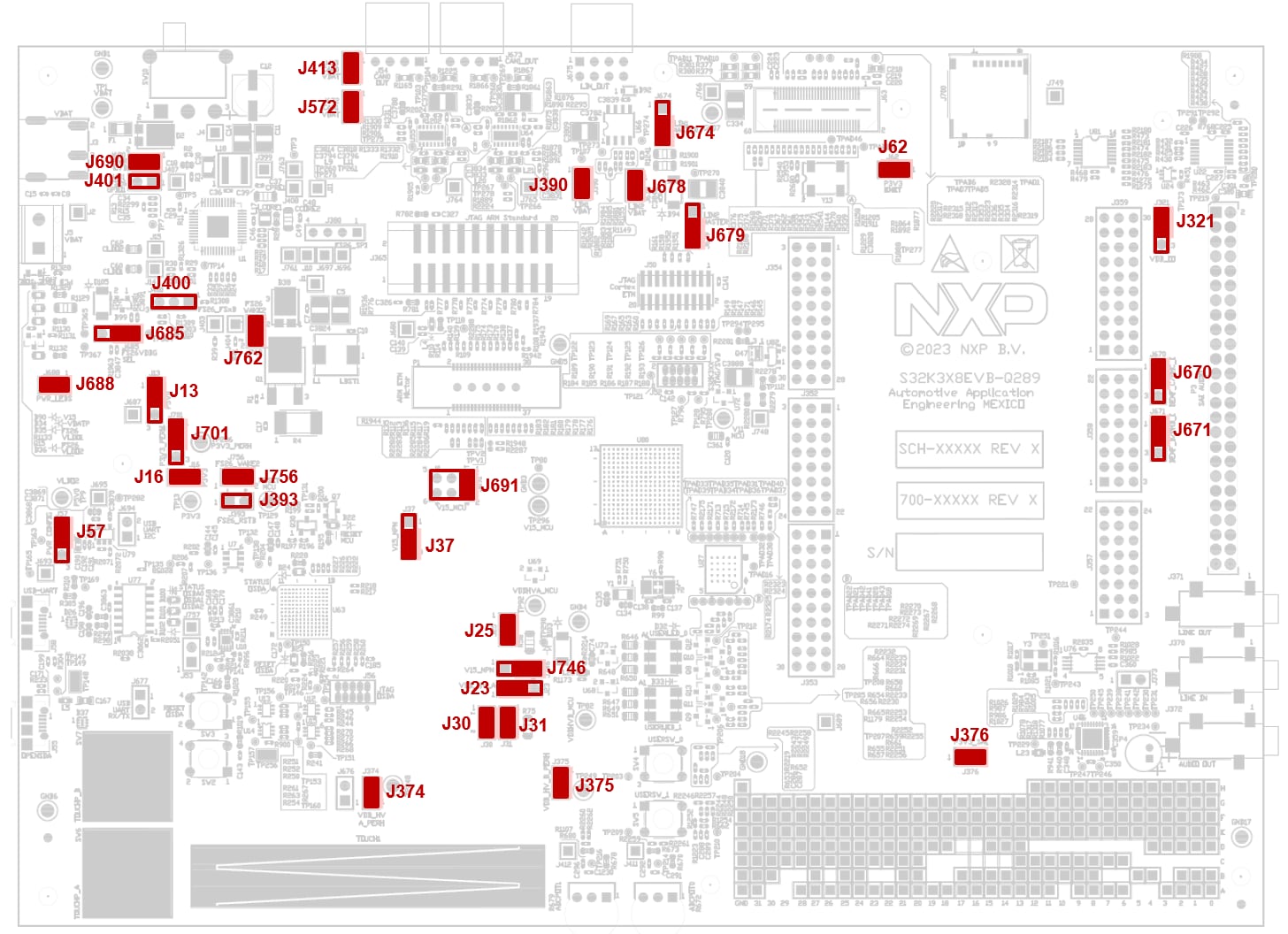
3.1 Set Up Jumpers in the S32K3X8EVB-Q289 Evaluation Board
| Default Jumpers settings | |||
|---|---|---|---|
| Interface | Reference | Position | Description / Comments |
| FS26/SBC Power Supply | J13 |
1-2 | FS26_VLDO1 [+5.0V] is routed to P5V0 domain |
J16 |
1-2 | FS26_VLDO2 [+3.3V] is routed to P3V3 domain | |
J701 |
1-2 | FS26_VTRK2 [+3.3V] is routed to P3V3_PERH domain | |
J685 |
1-2 | Select the debug mode of the FS26 | |
J688 |
1-2 | Power LED Indicators enabled | |
| S32K358 MCU | J23 |
1-2 | P5V0 (+5.0V from the FS26) is selected for the VDD_HV_A_MCU reference. |
J25 |
1-2 | VDD_HV_A is routed to VDD_HV_A_MCU reference. Remove R58 to enable J25 functionality. | |
J30 |
1-2 | P3V3 (+3.3V from the FS26) is selected for the VDD_HV_B_MCU reference. | |
J31 |
1-2 | VDD_HV_B is routed to VDD_HV_B_MCU reference. Remove R75 to enable J31 functionality. | |
J375 |
1-2 | VDD_HV_B is routed to VDD_HV_B_PERH | |
J374 |
1-2 | VDD_HV_A is routed to VDD_HV_A_PERH | |
J691 |
1-2 | V15_NPN [+1.5V] is routed to V15_MCU domain | |
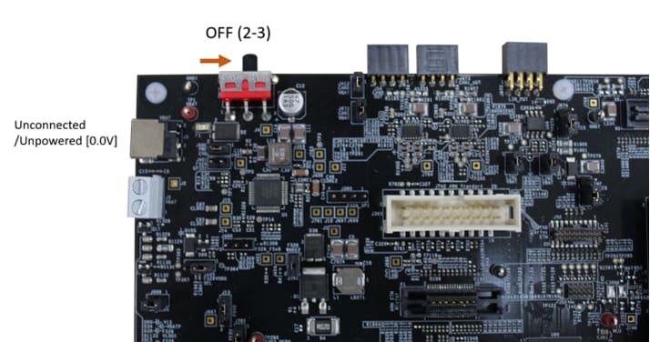
3.2 Plug In the Power Supply
Switch SW10 to the OFF position (fully to the right).
Connect the 12 V power supply adapter and switch SW10 to the ON position (fully to the left).
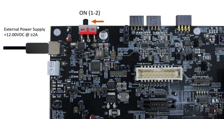
When power is applied to the EVB, four orange LED's adjacent to the voltage regulators show the presence of the supply voltages (12 V, 5 V and 3.3 V).
Design Resources
Software
- Automotive Software Package Manager
- S32K3 Standard Software Package
- S32K3 Reference Software Package
- S32 Design Studio IDE
- Real-Time Drivers (RTD)
- S32K Power Estimation Tool (PET)
- Model-Based Design Toolbox (MBDT)
- Structural Core Self-Test (SCST) Library
- FreeMASTER Run-Time Debugging Tool
- Inter-Platform Communication Framework (IPCF)
- Automotive Math and Motor Control Library (AMMCLib)
- S32 Safety Software Framework (SAF) and Safety Peripheral Drivers (SPD)
Training
- Getting Started with S32K3 using S32DS at the hello world project Training Presentation
- S32K3xx Pins and Clocks with RTD - Training
- S32K3xx Boot and Reset Sequence - Training
- S32K3xx Basic Bring-Up for AUTOSAR MCAL and Real-Time Drivers (RTD) Based on EB Tresos - Training
- S32K3xx Communication Modules FlexCAN - Training
- S32K3xx Communication Modules FlexIO - Training
- S32K3xx Security Overview and Bring Up - Training
- S32K3xx Safety Overview - Training
- How To Use the Automotive Software Package Manager
On this page
- 2.1
Get the Integrated Development Environment (IDE)
- 2.2
Install the S32K3xx Development Package and RTD
- 2.3
Download and Install Elektrobit tresos Studio and Real-Time Drivers (Only AUTOSAR Users)
- 2.4
Get the Run-Time Debugging Tool