Getting Started with the RDGD3162I3PH5EVB Evaluation Board
Contents of this document
-
Out of the Box
-
Get Hardware
-
Install Software
-
Configure Hardware
Sign in to save your progress. Don't have an account? Create one.

Purchase your RDGD3162I3PH5EVB
1. Out of the Box
The NXP analog product development boards provide an easy-to-use platform for evaluating NXP products. The boards support a range of analog, mixed-signal and power solutions. They incorporate monolithic integrated circuits and system-in-package devices that use proven high-volume technology. NXP products offer longer battery life, a smaller form factor, reduced component counts, lower cost and improved performance in powering state-of-the-art systems.
This page will guide you through the process of setting up and using the RDGD3162I3PH5EVB board.
1.1 Kit Content and Packing List
The RDGD3162I3PH5EVB contents include:
1.2 Additional Hardware
In addition to the kit contents, the following hardware is necessary or beneficial when working with this board.
- Microcontroller for SPI communication
- Compatible P6 IGBT or SiC metal-oxide-semiconductor field-effect transistor (MOSFET) module
- DC link capacitor compatible with HybridPACK drive or P6 IGBT or SiC MOSFET module
- HV power supply with protection shield and hearing protection
- Current sensors for monitoring each phase current
- 12 V, 1.0 A DC power supply
- 4-channel oscilloscope with appropriate isolated probes
1.3 Windows PC Workstation
This reference design requires a Windows PC workstation. Meeting these minimum specifications produces great results when working with this evaluation board:
- USB-enabled computer with Windows 8 or Windows 10
1.4 Software
Installing software is necessary to work with this reference design. All listed software is available at RDGD3162I3PH5EVB.
- FlexGUI software for using with KITGD316XTREVB MCU/translator board
- S32S Design Studio IDE for power architecture
- Automotive Math and Motor Control Library (AMMCLib)
- FreeMASTER 2.0 runtime debugging tool
- Motor control application tuning (MCAT)
- Example code, GD3162 device driver notes and GD31xx device driver reference
2. Get Hardware
2.1 Board Features
- Capability to perform double pulse and short-circuit tests on phase U using KITGD316XTREVB and FlexGUI
- Evaluation board designed for and populated with GD3162 gate drivers and protection circuitry
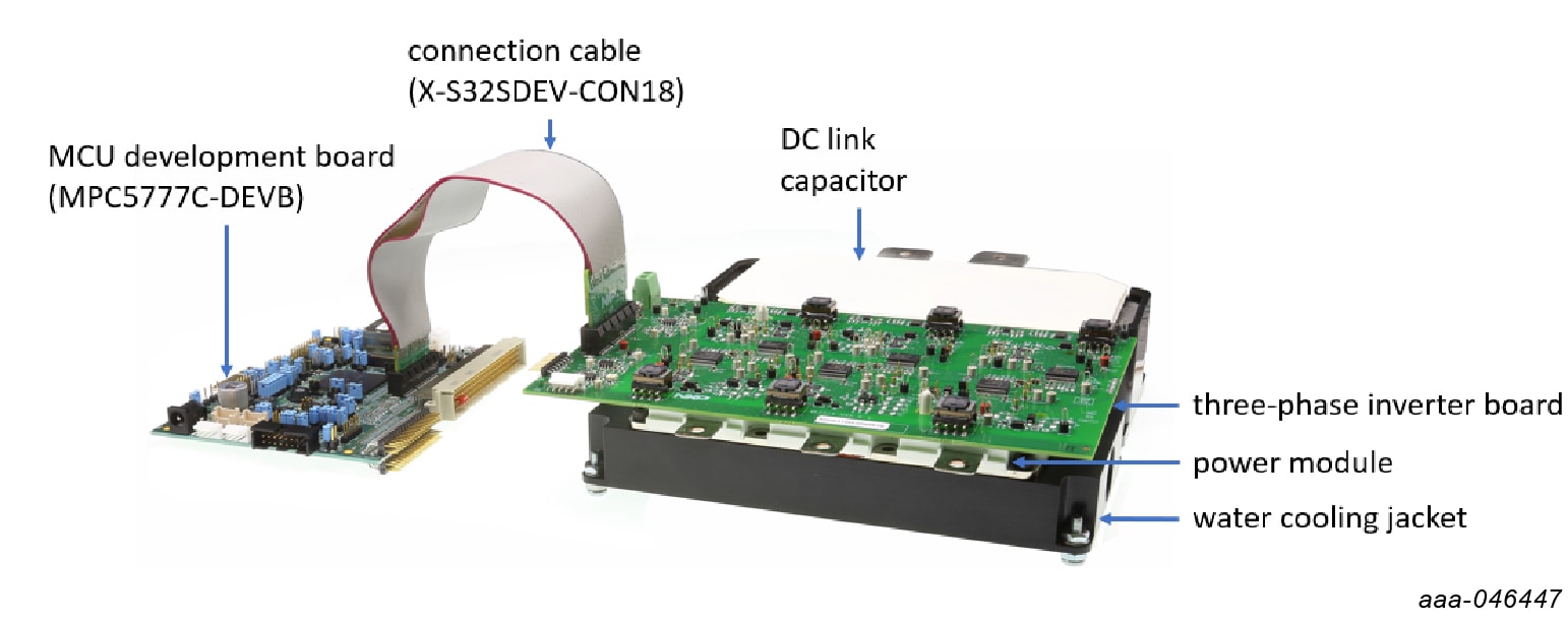
- Capability to connect to HybridPACK drive type SiC specific modules for full three- phase evaluation and development
- Daisy chain SPI communication x 3 - 2 channel (three high-side gate drivers and three low-side gate drivers) or x 6 - 1 channel (all six gate drivers)
- Variable flyback VCC power supply with GND reference and variable negative VEE supply
- Easy access power, ground and signal test points
- 2 x 32 Peripheral Component Interconnect Express (PCIe) socket for interfacing MCU control (MPC5775B/E-EVB, MPC5777C-DEVB or MPC57744P)
- Optional connection for DC bus voltage and current monitoring
- Phase current feedback connections
- Resolver signal connector
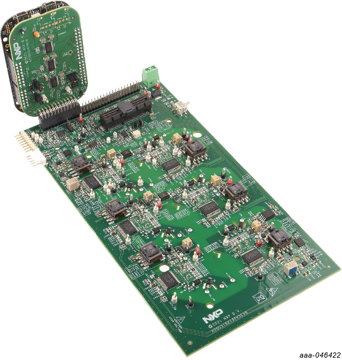
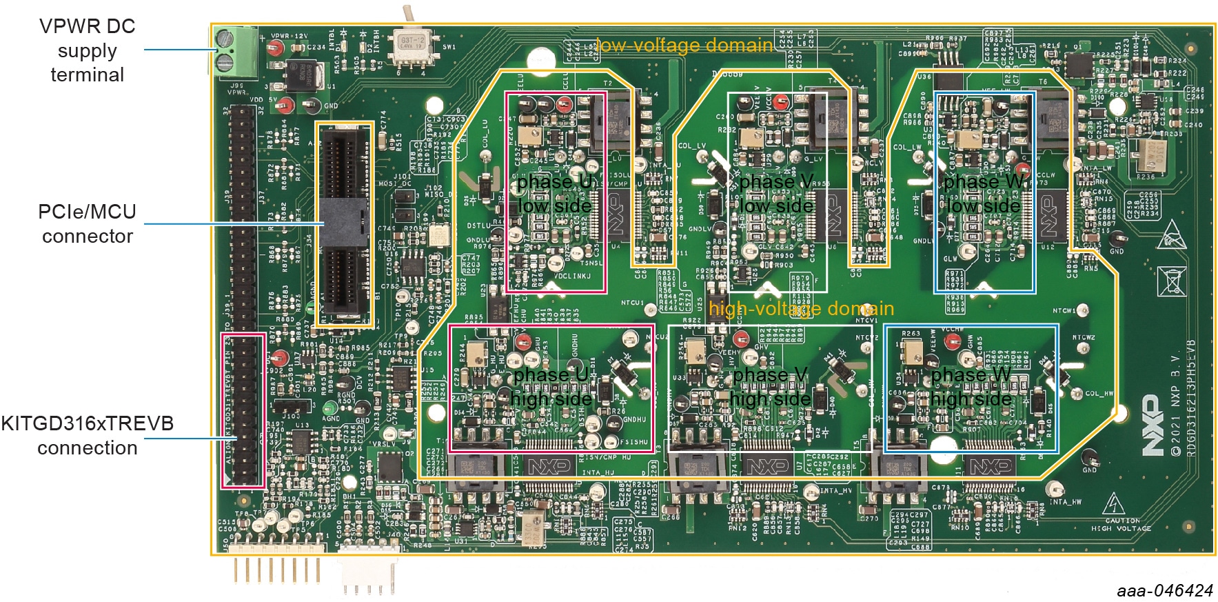
2.2 Board Description
The RDGD3162I3PH5EVB is a fully functional three-phase inverter evaluation board populated with six GD3162 gate drivers with fault management and supporting circuitry. This board supports serial peripheral interface (SPI) daisy chain communication for programming and communication with three high-side gate drivers and three low-side gate drivers independently, or all six gate drivers at the same time.
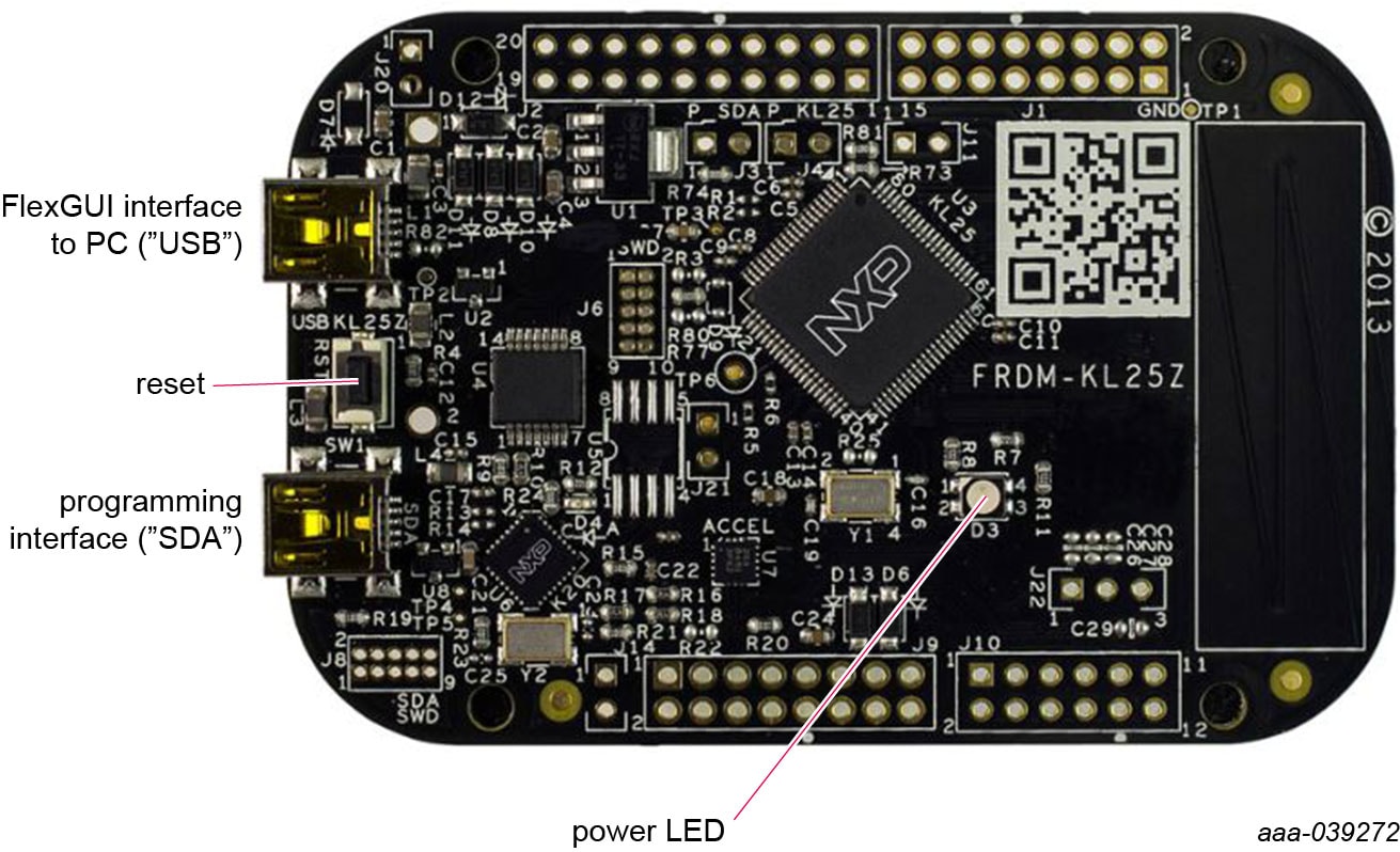
2.4 Kinetis KL25Z Freedom Board
The Freedom KL25Z is an ultra low-cost development platform for Kinetis L series MCU built on Arm Cortex-M0+ processor.
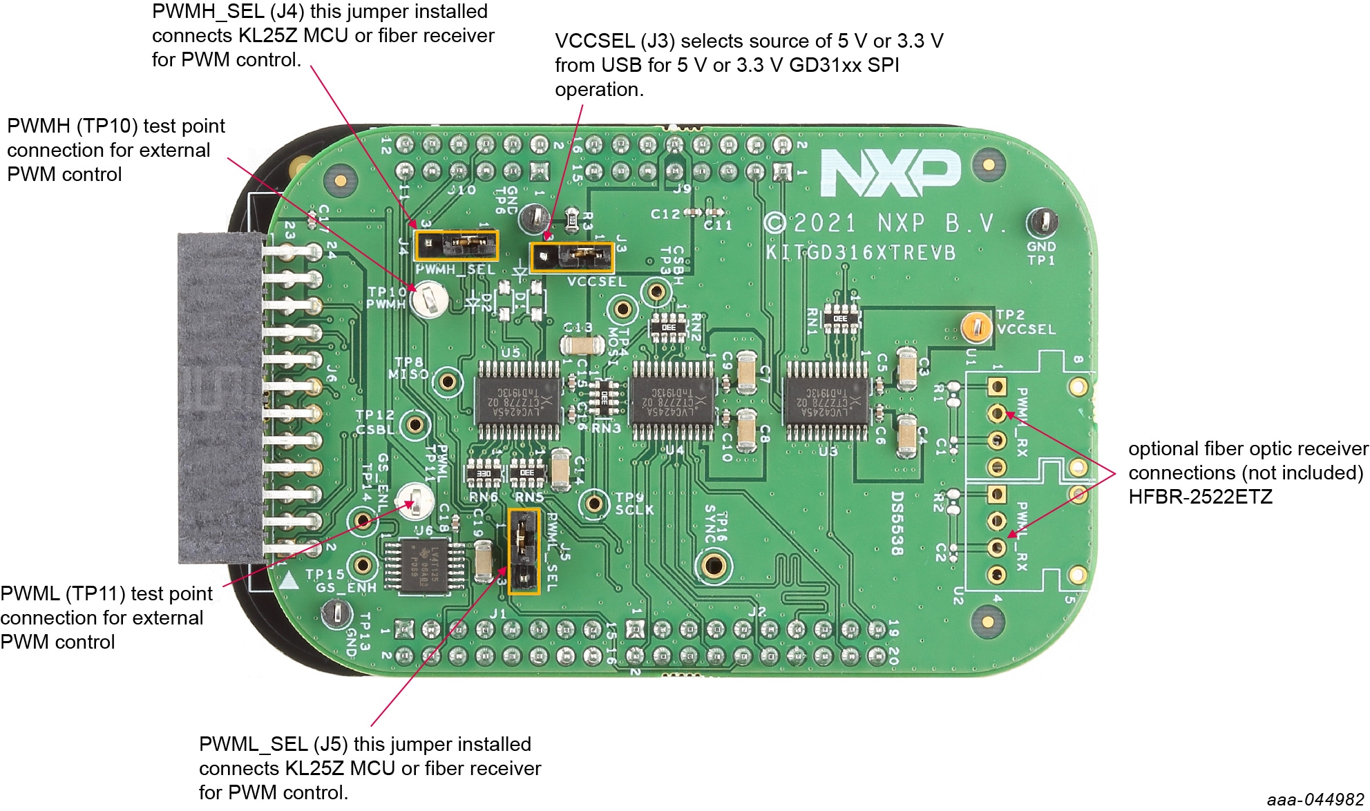
2.5 3.3 V to 5.0 V Translator Board
KITGD316XTREVB translator enables level shifting of signals from MCU 3.3 V to 5.0 V SPI communication.
| Jumper | Position | Function |
|---|---|---|
VCCSEL (J3) |
1-2 | selects 5.0 V for 5.0 V compatible gate drive |
| 2-3 | selects 3.3 V for 3.3 V compatible gate drive | |
PWMH_SEL (J4) |
1-2 | selects PWM high-side control from KL25Z MCU |
| 2-3 | selects PWM high-side control from fiber optic receiver inputs | |
PWML_SEL (J5) |
1-2 | selects PWM low-side control from KL25Z MCU |
| 2-3 | selects PWM low-side control from fiber optic receiver inputs |
3. Install Software
Software for RDGD3162I3PH5EVB is distributed with the FlexGUI tool (available on NXP). Necessary firmware comes pre-installed on the FRDM-KL25Z with the kit.
Even if the user intends to test with other software or PWM, it is recommended to install this software as a backup or to help debugging.
3.1 Install FlexGUI On Your Computer
The latest version of FlexGUI supports the GD3100, GD3160 and GD3162. It is designed to run on any Windows 10 or Windows 8 based operating system.
- Go to FlexGUI and click Download
- When the FlexGUI software page appears, click Download and select the version associated with your PC operating system
- FlexGUI wizard creates a shortcut, an NXP FlexGUI icon appears on the desktop. Installing the device drivers overwrites any previous FlexGUI installation and replaces it with a current version containing the GD31xx drivers. However, configuration files (.spi) from the previous version remain intact
3.2 Configuring the FRDM-KL25Z Microcode
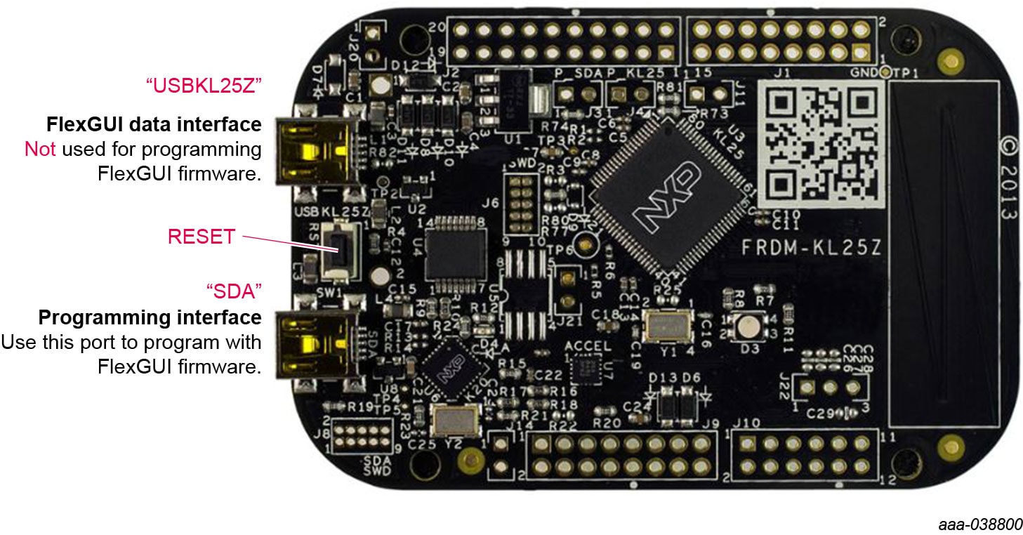
By default, the FRDM-KL25Z delivered with this kit is preprogrammed with the current and most up-to-date firmware available for the kit.
A way to check quickly that the microcode is programmed and the board is functioning properly, is to plug the KL25Z into the computer, open FlexGUI, and verify that the software version at the bottom is 6.4 or later (see Figure 3).
If a loss of functionality following a board reset, reprogramming or a corrupted data issue, the microcode is rewritten per the following steps:
- To clear the memory and place the board in bootloader mode, hold down the reset button while plugging a USB cable into the OpenSDA USB port
- Verify that the board appears as a BOOTLOADER device and continue with step 3. If the board appears as KL25Z, go to step 6
- Download the Firmware Apps.zip archive from the PEmicro OpenSDA webpage. Validate your email address to access the files
- Find the most recent MDS-DEBUG-FRDM-KL25Z_Pemicro_v118.SDA and copy/drag-and-drop into the BOOTLOADER device
- Reboot the board by unplugging and replugging the connection to the OpenSDA port. Verify now that the device appears as a KL25Z device to continue
- Locate the most recent KL25Z firmware; which is distributed as part of the FlexGUI package
- FlexGUI download file is named in the form “flexgui-fw-KL25Z_usb_hid_gd31xxC_vx.x.x.bin”
- This .bin file is a product/family-specific configuration file for FRDM-KL25Z containing the pin definitions, SPI/PWM generation code and pin mapping assignments necessary to interface with the translator board as part of RDGD3162I3PH5EVB
- With the KL25Z still plugged through the OpenSDA port, copy/drag-and-drop the .bin file into the KL25Z device memory. Once done, disconnect the USB and plug into the other USB port, labeled KL25Z
- The device does not appear as a distinct device to the computer while connected through the KL25Z USB port, which is normal
- The FRDM-KL25Z board is now fully set up to work with RDGD3162I3PH5EVB and the FlexGUI
- There is no software stored or present on either the driver or translator boards, only on the FRDM-KL25Z MCU board
All uploaded firmware is stored in non-volatile memory until the reset button is hit on the FRDM-KL25Z. There is no need to repeat this process upon every power up, and there is no loss of data associated with a single unplug event.
4. Configure Hardware
4.1 Configure the Hardware
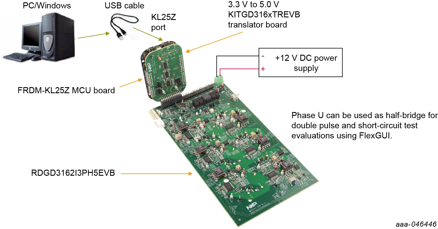
RDGD3162I3PH5EVB is connected to a KITGD316XTREVB translator board and a FRDM-KL25Z board as shown in the following figure.
Suggested equipment needed for test:
- Rogowski coil high-current probe
- High-voltage differential voltage probe
- High sample rate digital oscilloscope with probes
- DC link capacitor compatible with HybridPACK drive module
- IGBT or SiC MOSFET HybridPACK drive module
- Windows-based PC
- High-voltage DC power supply for DC link voltage
- Low-voltage DC power supply for VPWR – +12 V DC gate drive board low-voltage domain
- Voltmeter for monitoring high-voltage DC link supply
- Load coil for double pulse testing (phase U only)