Getting Started with the RD33774CNC3EVB Reference Design
Contents of this document
-
Out of the Box
-
Get Hardware
-
Configure Hardware
Sign in to save your progress. Don't have an account? Create one.
Purchase your HVBMS Centralized Cell Monitoring Unit Using CAN (FD) with MC33774 (CMU)
1. Out of the Box
The NXP analog product development boards provide an easy-to-use platform for evaluating NXP products. The boards support a range of analog, mixed-signal and power solutions. They incorporate monolithic integrated circuits and system-in-package devices that use proven high-volume technology. NXP products offer longer battery life, a smaller form factor, reduced component counts, lower cost, and improved performance in powering state-of-the-art systems.
This page will guide you through the process of setting up and using the RD33774CNC3EVB board.
1.1 Kit Contents and Packing List
The RD33774CNC3EVB kit contents include:
- Assembled and tested RD33774CNC3EVB board in an antistatic bag
- An electrical transport protocol link (ETPL) daisy chain cable
- A power and CAN interface cable
- Three cell interface cables
1.2 Additional Hardware
NXP offers the following board solutions to check the functionality of the devices and support the setup in testing the devices.
- BATT-18EMULATOR: 18-cell battery pack emulator
It is also possible to interface the RD33774CNC3EVB with the RD-K344BMU or RDK358BMU as part of the HWRD-HVBMSCC hardware reference design.
2. Get Hardware
2.1 Board Features
The main features of RD33774CNC3EVB are:
- CAN or CAN FD communication up to 5 Mbit/s to MC33665A
- Onboard CAN transceiver TJA1443
- Configurable CAN communication and CAN FD arbitration speeds on CFG0 and CFG1 pins using SW1 dual inline package (DIP) switch
- Configurable CAN ID (ID0_STB_OD, ID1, ID2, and ID3) for MC33665A using SW1 DIP switch
- Three MC33774 battery cell controllers
- Voltage monitoring and passive cell balancing functionality for up to 54 cells
- Capacitive isolation for daisy chain communication of onboard MC33774 devices and for offboard daisy chain communication
- Transformer isolation from TPL port 0 of MC33665A to MC33774
- Flexible configuration: single chain with loopback or two independent daisy chains without loopback
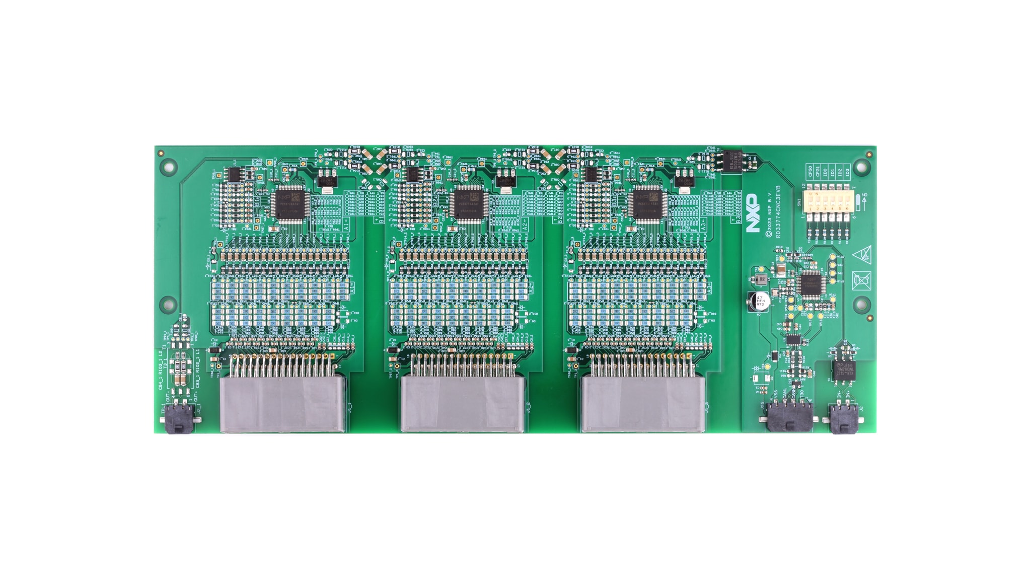
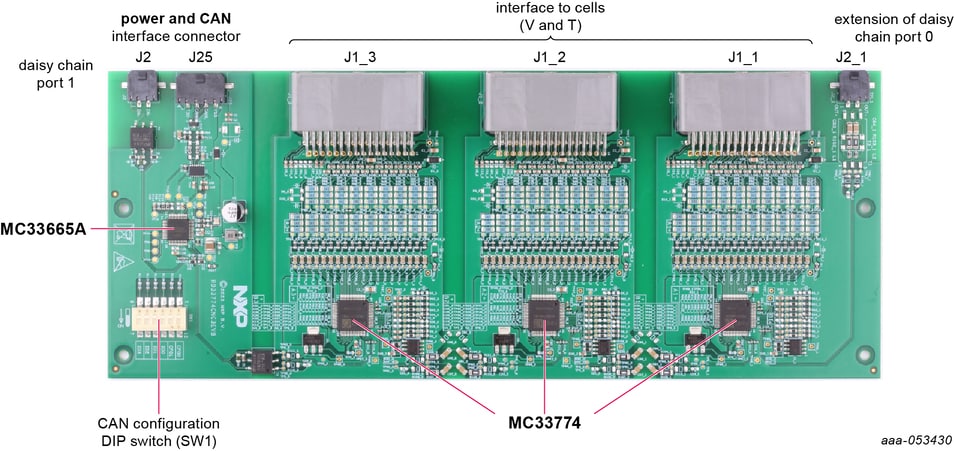
2.2 Board Description
The RD33774CNC3EVB is a CCMU reference design, which can communicate directly with CAN or CAN FD.
The MC33665ATF4AE populated on the RD33774CNC3EVB is a gateway router that can route transport protocol link (TPL) messages with CAN or CAN FD communication protocol. The MC33774 is a battery cell controller from NXP to monitor the cell voltages, temperatures, and passive balance. The RD33774CNC3EVB can monitor up to 54 cells onboard, and can be daisy-chained using an external TPL port for a higher number of cells.
3. Configure Hardware
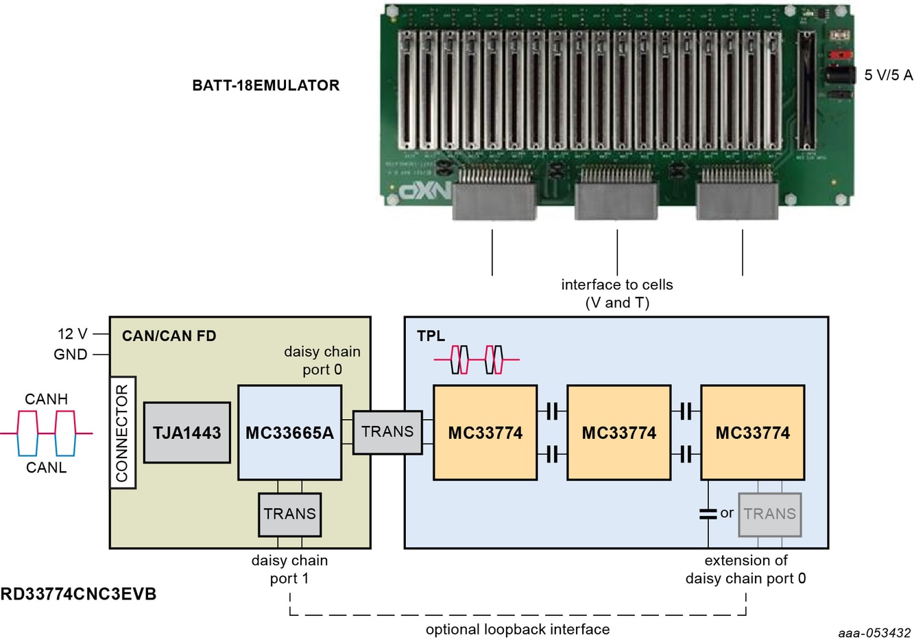
3.1 Standalone Test Setup
RD33774CNC3EVB can be used in different setup configurations to check the
performance of the MC33665A and the MC33774. Figure 1 is a minimal hardware
setup to check most of the functions and features built in RD33774CNC3EVB. The
BATT-18EMULATOR board can emulate a multicell (18 cells) battery pack that can be
easily connected to up to three BCC evaluation boards from NXP. Cell terminal and temperature (J1_1, J1_2 and J1_3) interface cable from
RD33774CNC3EVB are compatible to the BATT-18EMULATOR.
The J25 connector can be used to power the MC33665A and communicate with CAN or
CAN FD to the RD33774CNC3EVB. CAN tools can be interfaced to J25 for establishing
CAN or CAN FD communication with RD33774CNC3EVB.
- Set up the communication to RD33774CNC3EVB using the data sheets of the MC33665A and the MC33774
- Refer to Section 2.2 to set the CFG0, CFG1, ID0_STB_OD, ID1, ID2, and ID3 based on external CAN (FD) communication
- Based on test requirements, extra external MC33774 BCC boards can be connected to
RD33774CNC3EVB
- Connect to
J2_1as extension to daisy chain port 0 from third MC33774 - Connect to
J2as second daisy chain of BCC devices connected to port 1 of MC33665A
- Connect to
- Connect 5 V to BATT-18EMULATOR and 12 V to RD33774CNC3EVB after crosschecking the interface connections and boards based on test plan
3.2 RD33774CNC3EVB as Part of the HWRD-HVBMSCC
RD33774CNC3EVB is part of a hardware reference design for high voltages: HWRDHVBMSCC. To use the RD33774CNC3EVB in this environment, refer to the HWRDHVBMSCC user manual and website.
Design Resources
Additional References
In addition to our MC33774, 18 Channel Li-Ion Battery Cell Controller IC ASIL D page, you may also want to visit: