Getting Started with SC18IM704-EVB Evaluation Board
Contents of this document
-
Out of the Box
-
Get Hardware
-
Configure Hardware
Sign in to save your progress. Don't have an account? Create one.

Purchase your SC18IM704-EVB
1. Out of the Box
The NXP analog product development boards provide an easy-to-use platform for evaluating NXP products. The boards support a range of analog, mixed-signal and power solutions. They incorporate monolithic integrated circuits and system-in-package devices that use proven high-volume technology. NXP products offer longer battery life, a smaller form factor, reduced component counts, lower cost, and improved performance in powering state-of-the-art systems.
This page will guide you through the process of setting up and using the SC18IM704-EVB evaluation board.
2. Get Hardware
2.1 Board Features
- 9-pin D-SUB RS-232 style UART interface port (
J1) -
2-pin CMOS level UART interface (
JP5). Refer to SC18IM704 board user manual on how to selectJP5for UART interface - On-board I²C EEPROM and I²C blinker which can be directly accessed by the external UART via the SC18IM704
-
4-pin 100 mil spacing I²C interface header (
J2) to allow other I²C devices to be connected to the evaluation board to be accessed via the SC18IM704
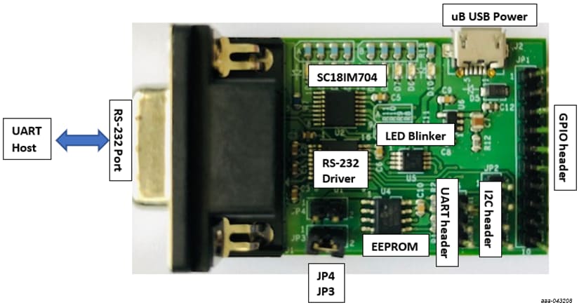
2.2 Board Description
The SC18IM704 evaluation board is designed to be connected to an
external UART via a 9-pin RS-232 connector (J1). The SC18IM704
evaluation board has an on-board I²C target serial
EEPROM and an I²C target LED blinker, which can be
directly accessed by the external host UART via SC18IM704. The
external host UART can write, read, and program the serial
EEPROM/LED blinker without requiring an I²C target to
be connected to the board.
The SC18IM704 evaluation board also has a I²C
interface header (JP2) to allow other I²C target
devices to be connected to the evaluation board. These
I²C target devices can be accessed directly by the
external host UART via the SC18IM704 UART to I²C
bridge.
The power for the evaluation board is provided via the micro-B
USB (J2), or via the I²C interface header (J2).
The SC18IM704 evaluation board 9-pin RS-232 port (J1) is
intended to be the main UART interface to the host’s UART, but
UART TX and RX CMOS level signals are available on JP5. When JP5
is used to interface to the host’s UART then the jumper on JP4
should be removed to remove power from the RS-232 line driver.
3. Configure Hardware
Design Resources
Additional Information
In addition to our SC18IM704, I²C-Bus to SPI Bridge page, you may also want to visit:
- UART pages: SC16IS752_SC16IS762, SC16IS741
- Hardware pages: Analog toolbox