8-bit General Purpose SE MCUs

Block Diagram

NXP S08SE Microcontroller Block Diagram

Freescale S08SE Microcontroller Block Diagram

Features

8-bit HCS08 Central Processor Unit (CPU)

  • Up to 20 MHz HCS08 (10 MHz internal bus frequency)
  • HC08 instruction set with added BGND instruction
  • Supports up to 32 interrupt/reset sources

Integrated Third-Generation Flash Memory and RAM

  • Embedded flash that is in-application reprogrammable over the full operating voltage and temperature range with a single power supply
  • Fast, byte-writable programming, as fast as 20 µs (burst mode)
  • Up to 100,000 write/erase cycles at typical voltage and temperature (10k minimum write/erase)
  • 100 years typical data retention (15 years minimum)

Flexible Clock Options

  • Internal clock source (ICS) module with a frequency-locked loop (FLL) controlled by internal or external reference
  • Precision trimming of internal reference allows typical 0.2 percent resolution and 2 percent deviation over operating temperature and voltage
  • Internal reference can be trimmed from 31.25 kHz to 38.4 kHz, allowing for up to 10 MHz FLL output
  • Low-power oscillator module (XOSC) with software-selectable crystal or ceramic resonator range, 31.25 kHz to 38.4 kHz or 1 MHz to 16 MHz

22 I/O Pins, One Input-Only Pin and One Output-Only Pin

  • Outputs 10 mA each, 60 mA max for package
  • Software-selectable pull-ups on ports when used as inputs; internal pull-up on reset and interrupt request (IRQ) pin
  • Software-selectable slew rate control and drive strength on ports when used as output
  • 8-pin keyboard interrupt module with softwareselectable polarity on edge or edge/level modes

Ganged Output Option for PTB (5:2) and PTC (3:0)

  • Allows single write to change state of multiple pins
  • Provides option to tie multiple pins from different ports to same control registers

Multiple Serial Communication Options

  • Serial communication interface module with option for 13-bit break capabilities and double-buffered transmit and receive

Analog-to-Digital Converter (ADC)

  • 10-channel
  • 10-bit
  • Automatic compare function, software programmable for greater than, equal to or less than conditions
  • Asynchronous clock source
  • Temperature sensor
  • Hardware triggerable using the RTC counter
  • Low-power and high-speed options

Real-Time Counter (RTC)

  • 8-bit modulus counter with binary or decimal-based prescaler
  • Three software selectable clock sources
    • 1 kHz internal low-power oscillator
    • External clock and 32 kHz internal clock

Three Timer Modules

  • Programmable 16-bit timer/PWM modules (TPM1 and TPM2)

System Protection

  • Watchdog computer operating properly (COP) reset with option to run from dedicated 1 kHz internal clock source or bus clock
  • Low-voltage detection with reset or interrupt
  • Illegal opcode detection with reset
  • Security feature for flash and RAM
  • Always-on power-on reset (POR) circuitry

Development Support

  • Background debugging system
  • On-chip in-circuit emulation (ICE) with real-time bus capture

Buy/Parametrics


Documentation

Quick reference to our documentation types.

1-5 of 22 documents

Show All

Design Files

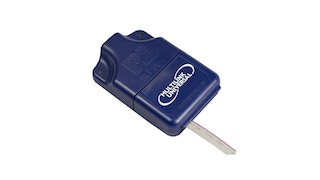
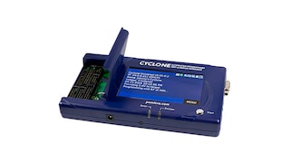
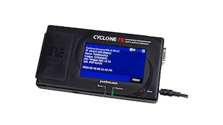
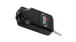
Hardware

Quick reference to our board types.

5 hardware offerings

Software

Quick reference to our software types.

1-5 of 10 software files

Show All

Note: For better experience, software downloads are recommended on desktop.

Engineering Services

2 engineering services

To find additional partner offerings that support this product, visit our Partner Marketplace.

Support