Getting Started with the TJA11xx-SDBx Evaluation Board Family
Contents of this document
-
Out of the Box
-
Get Hardware
-
Install Software
-
Configure Hardware
Sign in to save your progress. Don't have an account? Create one.
Purchase your TJA11xx-SDBx
1. Out of the Box
The NXP analog product development boards provide an easy-to-use platform for evaluating NXP products. The boards support a range of analog, mixed-signal and power solutions. They incorporate monolithic integrated circuits and system-in-package devices that use proven high-volume technology. NXP products offer longer battery life, a smaller form factor, reduced component counts, lower cost and improved performance in powering state-of-the-art systems.
This page will guide you through the process of setting up and using the TJA11xx-SDBx family of boards.
1.1 Kit Contents and Packing List
The kit contents include:
- Assembled and tested TJA11xx-SDBx evaluation board in an antistatic bag
- UTP cable with 2 x MateNET connectors
1.2 Additional Hardware
In addition to the kit contents, the following hardware is needed when working with this kit.
- A host board
1.3 Software
The TJA11xx-SDBx board can be used on any platform that contains a SABRE connector and that supports the relevant xMII interface. The most commonly used platforms are:
- Linux-based platforms: S32Gxx boards/i.MX board - drivers are included in the mainline Linux kernel
- Platforms supported by SDK (S32DS): S32K1xx / S32K3xx - SDK Real-Time Drivers are available
- Hardware evaluation in combination with TJA11xx-EVB board - AES EVB GUI or Python command-line tooling available
2. Get Hardware
2.1 Board Features
- Quick functional evaluation of TJA1103 and TJA1104 (100BASE-T1) and TJA1120 and TJA1121 (1000BASE-T1)
- Supports MACsec (TJA1104 and TJA1121)
- Supports MII/RMII/RGMII (PN ending with R)
- Supports SGMII (PN ending with S)
- SMA and JTAG connectors
- Voltage and current tap points
- Control signals accessible via pin headers
- Config pin strapping jumper settings
- Control signals for inhibit and wake in/out
- Multiply supply options
2.2 Board Description
The TJA11xx-SDBx family of evaluation boards is intended to help familiarize the user with TJA1103, TJA1104, TJA1120 and TJA1121 PHYs from NXP. Each of the eight available boards is populated with one of these devices. The SDBR boards support CMOS-based MII, RMII and RGMII MAC interfaces. The SDBS boards feature an SGMII MAC interface.
Configuration options are selected via jumpers. GPIO and control signals are accessible via pin headers for evaluation and debugging purposes. In addition, a number of tap points are provided to enable current and voltage measurements to be taken on the supply rails.
3. Install Software
3.1 Install Software
The board can be used on any platform that has a SABRE connector and that supports the required xMII interface. Depending on the use case, the required software can be downloaded from NXP.
- Linux-based platforms: S32Gxx boards/i.MX board - drivers are included in the TJA11xx Linux driver for IEEE 802.3 Clause 45 managed PHYs, which can be downloaded from secure files at the specific PHY product page, for example TJA1103
- Platforms supported by SDK (S32DS): S32K1xx / S32K3xx SDK Real-Time Drivers are included in TJA11XX Ethernet Phy Real-Time Drivers AUTOSAR® 4.4, which can be downloaded from secure files files at the specific PHY product page, for example TJA1103
4. Configure Hardware
4.1 Configure Hardware
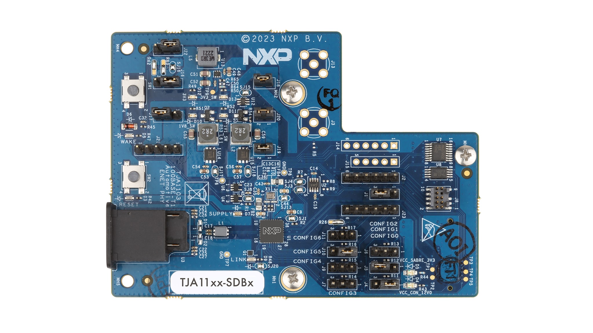
Before plugging the SDBx board onto a host board, it should be configured as illustrated in Figure 2 and described in Table 1. For this example, the TJA1104-SDBS board has been taken.
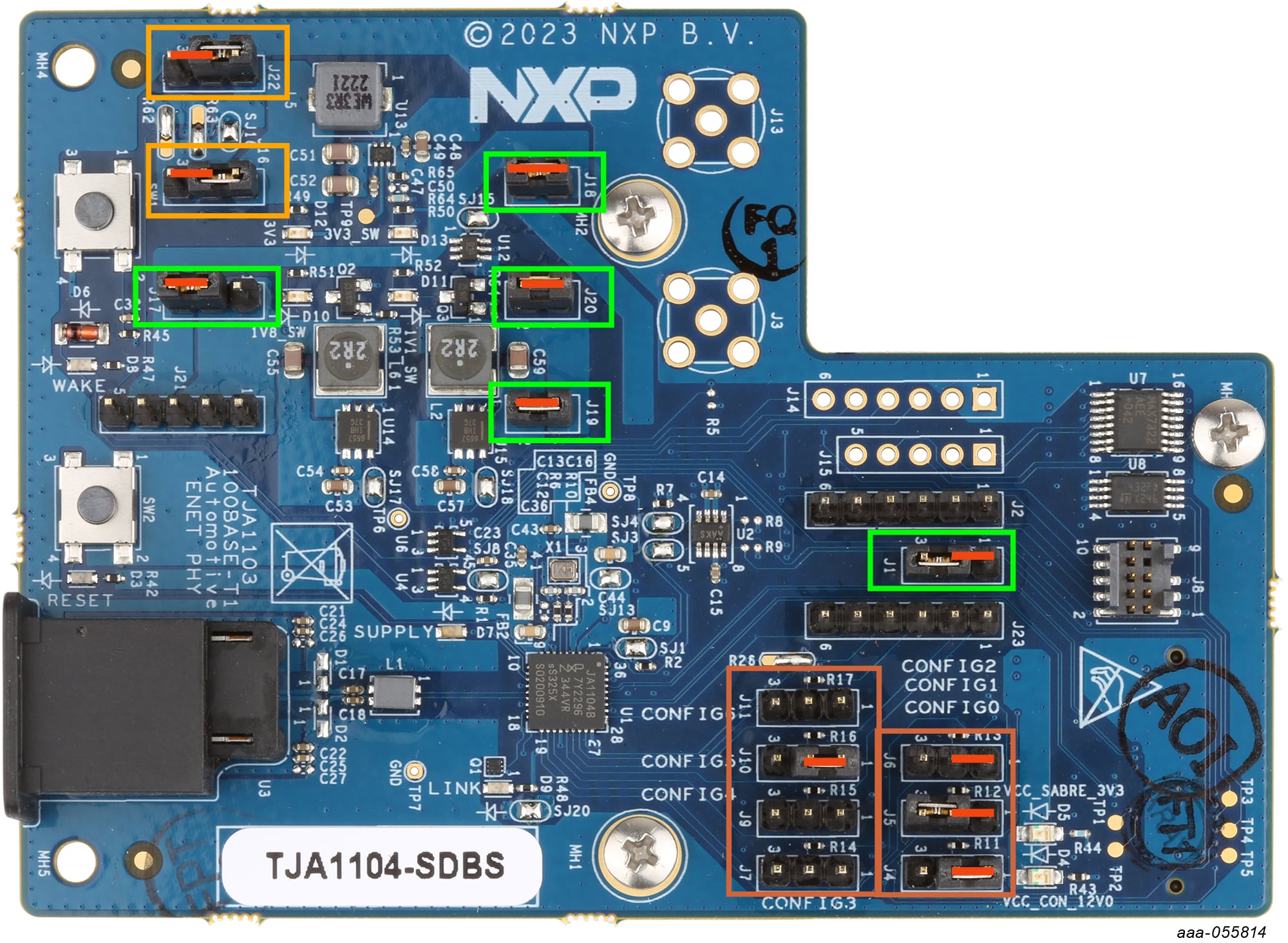
| Function | Setting | Description | |
|---|---|---|---|
| Supply input | J16: 2-3J22: 2-3 |
Entire board powered by 3.3 V supply from host board. |
|
| Supply concept |
J1: 1-2
J17: 2-3
J18: 1-2
J19: 1-2
J20: 1-2
|
VDDIO = 3.3 V Supplies always enabled All supply rails connected |
|
| Pin strapping |
J4/CONFIG0: 1-2
J5/CONFIG1: 1-2
J6/CONFIG2: 1-2
J7/CONFIG3: open
J9/CONFIG4: open
J10/CONFIG5: 1-2
J11/CONFIG6: open
|
||
| TJA1103/04 | TJA1120/21 | ||
| PHYAD=1 RGMII RXC-ID Nonautonomous responder |
PHYAD=1 RGMII RXC-ID Xtal Clock Autonomous controller |
||
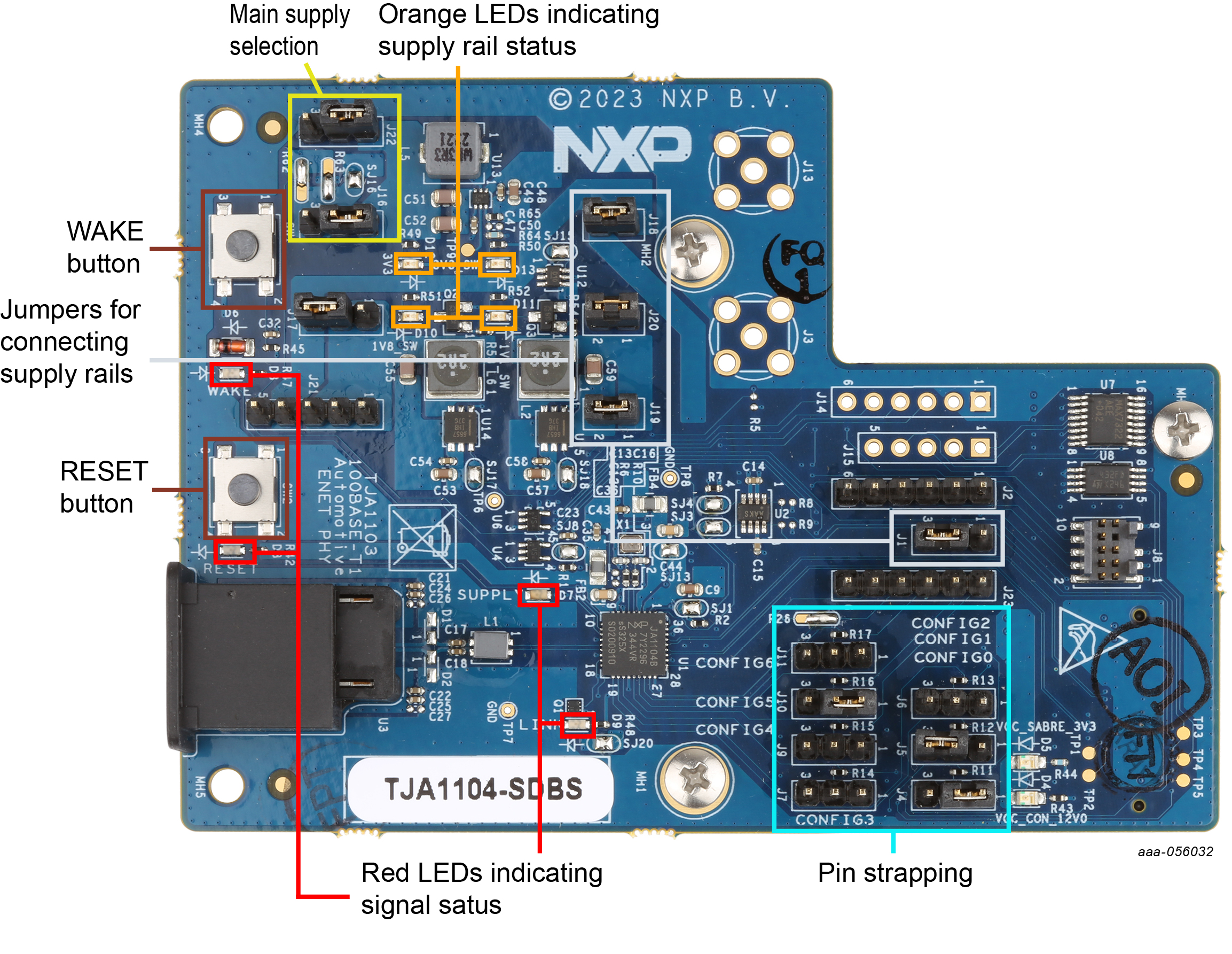
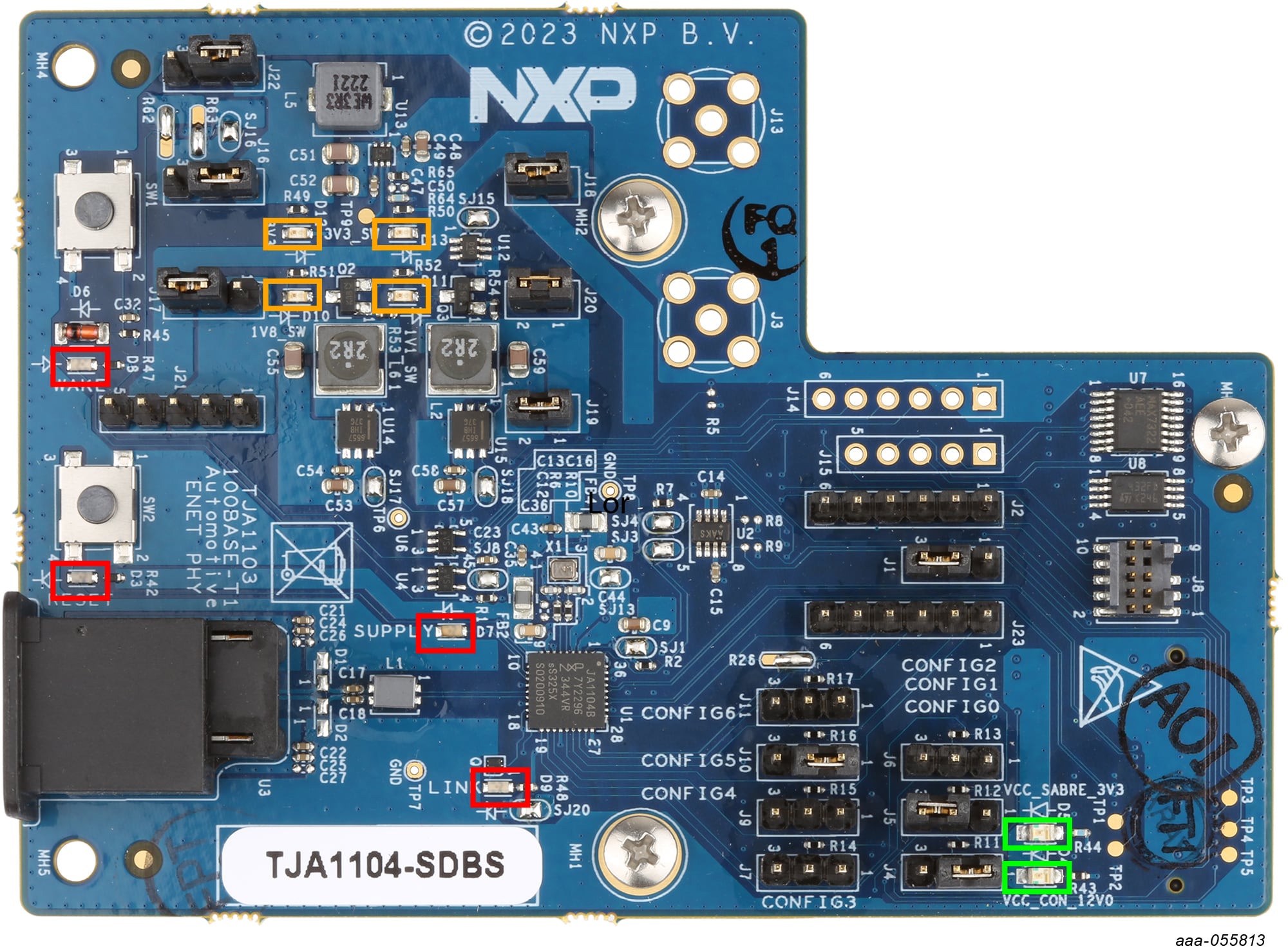
After plugging the SDBx board onto the host board and powering it up, check the following LEDs:
- Green:
D5- on indicates the 3.3 V supply from the host board is active (via the SABRE connector) - Orange:
D10,D11,D13- indicate supply rail status (1V8, 1V1, 3V3; on = available) - Red:
D7- on indicates that the PHY is active (active-HIGH) - Red:
D9- indicates link status (active-HIGH) - Red:
D3,D8- reset and wake status (active-LOW, active-HIGH)
If the power indicator LEDs indicate that the board is in the required state, an Ethernet cable and link partner can be connected. If the link partner is active and configured as a responder, a link should be established without the need for software configuration.
Design Resources
Board Information
Available to selected customers only (non disclosure agreement (NDA) required). Contact your local NXP sales representative for more information.
Additional References
In addition to our Automotive Ethernet PHY Transceivers product pages containing details of our PHY devices, you may also want to visit: