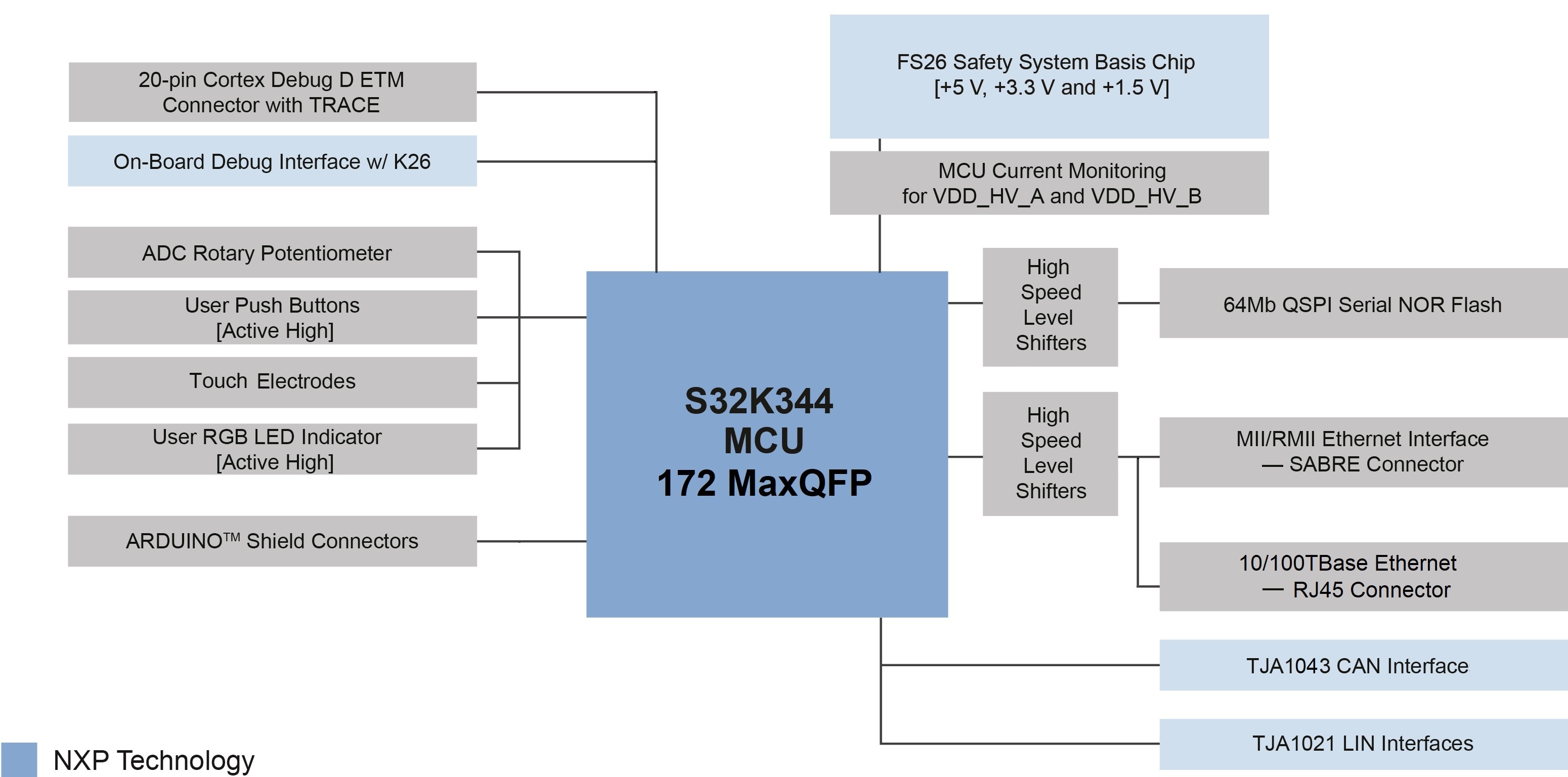
Getting Started with the S32K3X4EVB-Q172 Evaluation Board
Contents of this document
-
Out of the Box
-
Get Software
-
Plug It In
-
Build, Run
Sign in to save your progress. Don't have an account? Create one.

Purchase your S32K3x4-Q172 General-Purpose Development Board

2. Get Software
You can watch the video or follow the below step-by-step guide to set up your S32K3X4EVB-Q172 Evaluation Board:
2.1 Get the Integrated Development Environment (IDE)
Download and Install S32 Design Studio IDE for S32 Platform.
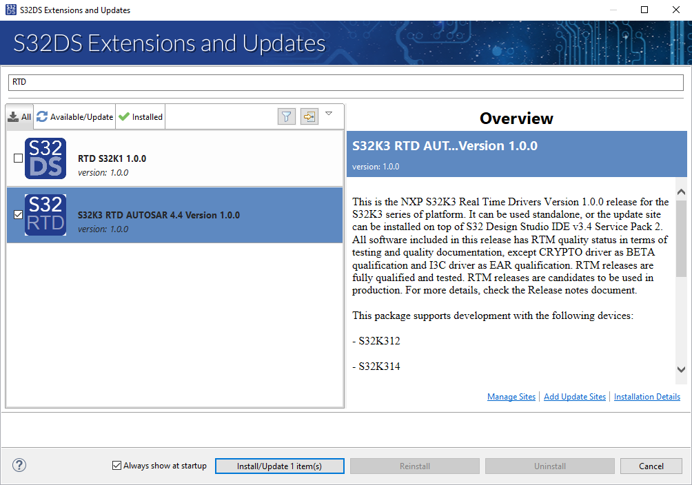
2.2 Install the S32K3xx Development Package
Go to Help → S32DS Extensions and Updates from the top menu to open the S32DS Extensions and Updates. Navigate to the S32K3xx development package and install it.

Continue with the installation of the Real-Time Drivers for S32K3xx:
2.3 Download and Install Elektrobit Tresos Studio and Real-Time Drivers (Only AUTOSAR® Users)
Download and install Elektrobit Tresos Studio / AUTOSAR Configuration Tool from S32K3 Standard Software Package.
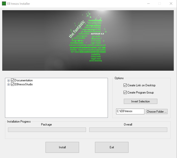
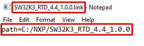
Download and install the .exe file of the S32K3 Real-Time Drivers for Cortex-M from the S32K3 Standard Software Package.
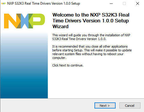
The installer will ask for the EB Tresos installation directory on your disk, saving time in configuration.
2.4 Get the Run-Time Debugging Tool
S32K3X4EVB-Q172 performs better when using the FreeMASTER Run-Time Debugging Tool.
The FreeMASTER communication driver for S32K3 microcontrollers is also needed; download it from the Automotive SW - S32K3 - S32 FreeMASTER link in the S32K3 Standard Software Package.
3. Plug It In
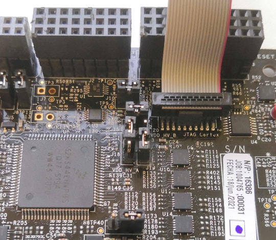
3.1 Set Up Jumpers in the S32K3X4EVB-Q172 Evaluation Board

| Default Jumper settings | ||
|---|---|---|
| Jumper | State | Notes |
J1 |
CLOSED | Disabled FS26 watchdog after power-up |
J5 |
1-2 | Select voltage level for FS26 DEBUG pin |
J8 |
CLOSED | External circuits powered from VDD_HV_B domain |
J9 |
CLOSED | External circuits powered from VDD_HV_A domain |
J10 |
CLOSED | The MCU peripherals powered from the VDD_HV_A domain |
J15 |
CLOSED | The MCU peripherals powered from the VDD_HV_B domain |
J18 |
1-2 | 5 V for the VDD_HV_A domain |
J19 |
1-2 | 3.3 V for the VDD_HV_B domain |
J20 |
OPEN | LIN1 Controller mode |
J22 |
1-2 | 5 V from FS26 SBC |
J24 |
OPEN | LIN2 Controller mode |
J26 |
CLOSED | 3.3 V from FS26 SBC |
J30 |
OPEN | FS26 wake inputs |
J31 |
1-2 | V15 domain powered from FS26 SBC |
J44 |
OPEN | Onboard debugger UART pins |
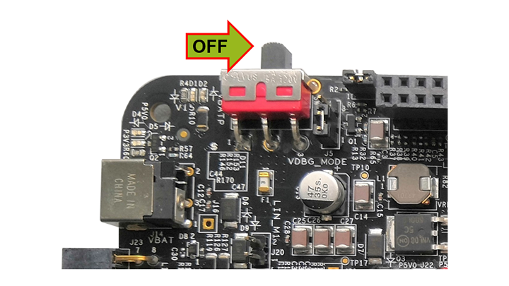
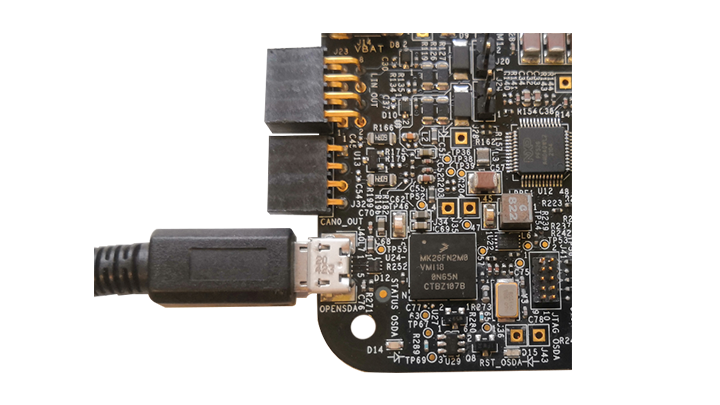
3.2 Plug in the Power Supply
Switch SW1 to the OFF position (fully to the right).
Connect the 12 V power supply adapter and switch
SW10 to the ON position (fully to the left).
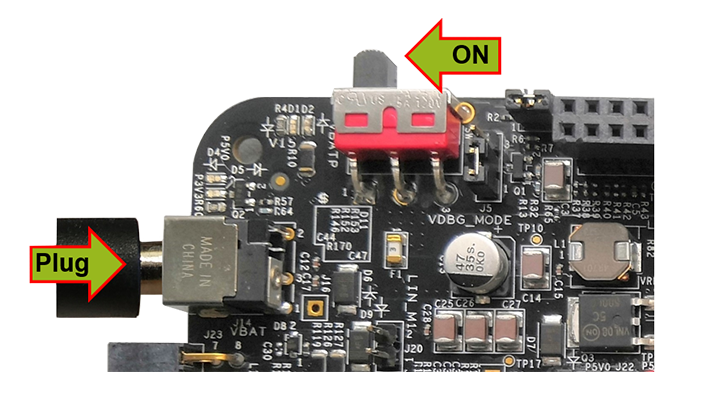
This power-up procedure manages that SBC starts with the disabled watchdog. Four orange LEDs indicate the active 12 V, 5 V, 3.3 V and 1.5 V power supply domains.
4. Build, Run
Let's take your S32K3X4EVB-Q172 Evaluation Board for a test drive.
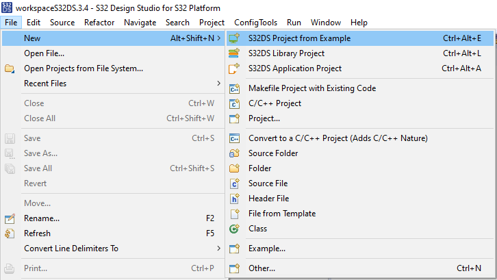
4.1 Create a S32DS Project from Example
Open S32DS and from the menu, go to: File → New → S32DS Project from Example. Select one of the RTD example codes. You may choose between examples with a high-level API or with a low-level API. For example: Port_example_K344.
4.2 Using the Configuration Tool
Double-click on the .mex project file.
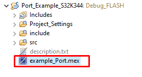
Please ensure that you configure the appropriate project and click on "Update Code" button for generating configuration files.

4.3 Upload Software and Debug
Return back to the C/C++ perspective.
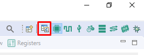
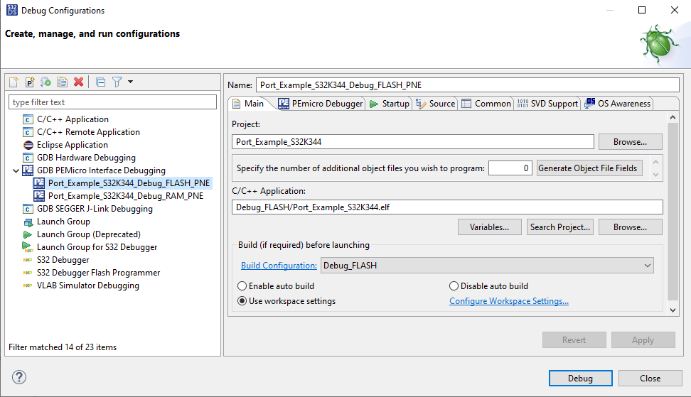
Use the Debug Configuration menu and select one of the predefined debug configurations for building and uploading software into MCU.

The S32DS will switch into Debug perspective where you may let the code run.
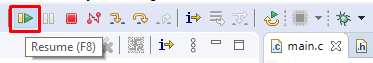
The red LED will now blink for approximately 10 seconds.
Support
Trainings
- Introducing the S32K3 Automotive MCU family
- High Voltage Battery Management System NXPLive Demo
- Twelve-Phase PMSM or Multimotor Applications with S32K3 MCU
- High-voltage BMS solution using the S32K3 MCU, FS26 SBC and MC3377x cell controller
- Body Domain Controller Solution with the S32K3 MCU, FS26 SBC, SJA1105 Transceiver and CD1030 MSDI
On this page
- 2.1
Get the Integrated Development Environment (IDE)
- 2.2
Install the S32K3xx Development Package
- 2.3
Download and Install Elektrobit Tresos Studio and Real-Time Drivers (Only AUTOSAR® Users)
- 2.4
Get the Run-Time Debugging Tool