Getting Started with the RD-HVBMSCTBUN Reference Design
Contents of this document
-
Out of the Box
-
Get Hardware
-
Configure Hardware
Sign in to save your progress. Don't have an account? Create one.

Purchase your HVBMS | Reference Design Bundle (RD-HVBMSCTBUN)
1. Out of the Box
The NXP analog product development boards provide an easy-to-use platform for evaluating NXP products. The boards support a range of analog, mixed-signal and power solutions. They incorporate monolithic integrated circuits and system-in-package devices that use proven high-volume technology. NXP products offer longer battery life, a smaller form factor, reduced component counts, lower cost and improved performance in powering state-of-the-art systems.
This page will guide you through the process of setting up and using the RD-HVBMSCTBUN reference design.
1.1 Kit Content and Packing List
The RD-HVBMSCTBUN contents include:
- Battery management unit kit
- One RD-K344BMU board
- One power supply (12 VDC, 5.0 A)
- One multipurpose cable
- One USB-TTL cable
- One ETPL cable
- Cell monitoring unit kit
- One RD33775ACNTEVB board
- Four supply cables
- One ETPL cable
- Battery junction box kit
- One RD772BJBTPLEVB board
- One power cable
- Three high voltage measurement cables
- One thermal sensor cable
- One ETPL cable
- Battery emulation kit
- One BATT-14CEMULATOR board
- One power supply (12 VDC, 5.0 A)
- One adapter
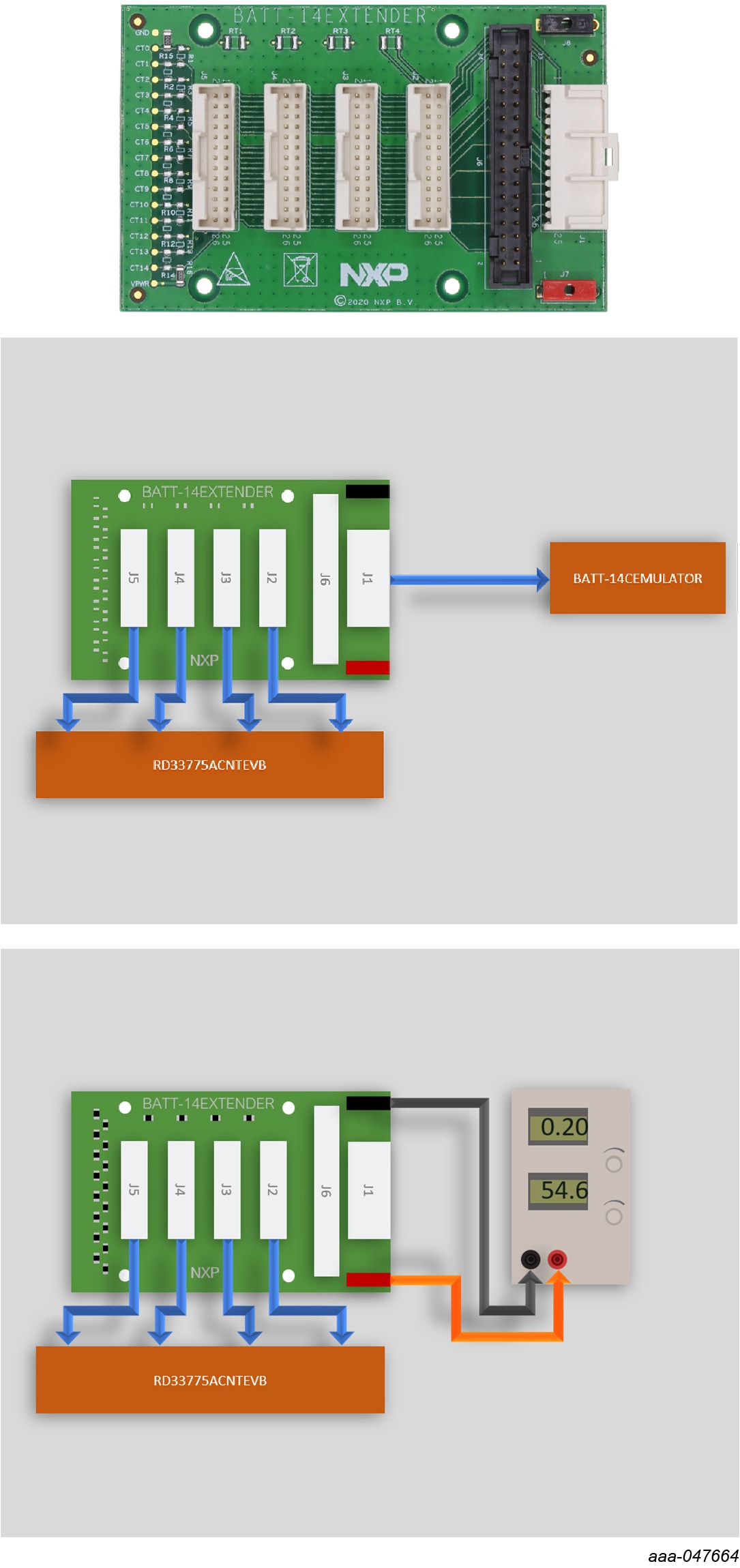
- One BATT-14EXTENDER board
- One supply cable
- Software license
An HVBMS start-up Interface is available on the HVBMS Reference Design Bundle website to visualize cell voltage measurements at first start-up. This interface is a GUI running on FreeMASTER (NXP Run-Time Debugging Tool) matching with a binary file that is preflashed on the BMU.
1.2 Additional Hardware
In addition to the kit contents, the following hardware is necessary or beneficial when working with this kit.
- A PC to run the provided graphical user interface (GUI) and program the RD- K344BMU board
- A JTAG debugger, to program the RD-K344BMU board. The recommended debugger is a PE Micro Multilink FX
- An external power supply to use the BATT-14EXTENDER in voltage divider mode (optional)
2. Get Hardware
2.1 Description
The RD-HVBMSCTBUN is a high voltage battery management system (HVBMS) reference design bundle. It has been developed for evaluation and development purposes. It is composed of a hardware kit and several software packages.
2.2 Battery Management Unit
The battery management unit (BMU) is the control part of the battery management system (BMS). The BMU processes the data, makes decisions and commands the system.
The RD-K344BMU is the HVBMS reference design BMU. This BMU kit includes a power supply and three cables to interface with other parts of the HVBMS.


To learn more about the RD-K344BMU, visit the website associated with this reference design.
2.3 Firmware Version
The RD-K344BMU is preflashed with firmware to ease start-up. From firmware version 0.9.1, a sticker has been added on the RD-K344BMU board and packing box to mention the firmware version included. If the sticker does not mention the version of your board, it has been preflashed with the firmware version 0.8.0.
- Firmware version 0.8.0 does not include System Basis Chip (SBC) support. The SBC needs to be set in Debug mode at start-up by pressing the SW1 button. Having the SBC in the incorrect mode causes the MCU to cyclically reset and the LEDs to blink. This firmware version is not compatible with the latest version of the HVBMS start-up interface described in this guide. You can either use the previous version or reprogram the MCU with the latest .elf file included in the latest HVBMS bring-up example
- Firmware version 0.9.1 and newer includes SBC support. SBC is in Normal mode by default and works with the HVBMS start-up application. Nevertheless, the SBC should be placed in Debug mode by pressing the SW1 button at power-on reset in order to allow reflash of the MCU
2.4 Cell Monitoring Unit
The cell monitoring unit (CMU) is the cell-sensing part of the battery management system. The CMU precisely monitors cell voltages and environmental temperatures to ensure safe battery operation and enables fast cell balancing.
The RD33775ACNTEVB is the HVBMS reference design CMU for electrical transport protocol link (ETPL) based architectures. This CMU kit includes five cables to interface with other parts of the HVBMS.


2.5 Battery Junction Box
The battery junction box (BJB) is the pack-level sensing part of the battery management system. The BJB measures high voltages. This measurement allows monitoring connections of the contactors to the inverter and the charger. The BJB also precisely measures the system’s current and monitors the battery to chassis isolation.
The RD772BJBTPLEVB is the HVBMS reference design BJB for electrical transport protocol link (ETPL) based architectures. This BJB kit includes six cables to interface with other parts of the HVBMS.


3. Configure Hardware
3.1 Configure Hardware
The procedure for connecting and setting up the system is as follows:
- Connections of the boards:
- Unpack all boards and cables from the kit
- Connect the multipurpose cable onto the RD-K344BMU (
J1) - Connect the Cell Monitoring Unit (CMU)
- Connect the first ETPL cable to the RD-K344BMU (
J2) and the RD33775ACNTEVB (J37) - Connect the second ETPL cable to the RD-K344BMU (
J3) and the RD33775ACNTEVB (J30) - Connect the four supply cables to the RD33775ACNTEVB (
J1,J34,J35andJ36) and the BATT-14EXTENDER (J2,J3,J4andJ5) - Connect the supply cable to the BATT-14EXTENDER (
J1) and the BATT-14CEMULATOR (J1)
- Connect the first ETPL cable to the RD-K344BMU (
- Connect the Battery Junction Box (BJB).
- Connect the ETPL cable between the RD-K344BMU (
J5) and the RD772BJBTPLEVB (J9) - Connect the BJB supply cable between the RD-K344BMU (
J1, 4-pin connector, pins 11 to 14) and the RD772BJBTPLEVB (J12)
- Connect the ETPL cable between the RD-K344BMU (
- Powering the boards:
- Power the CMU and the battery emulation system, by powering the
BATT-14CEMULATOR using the provided power supply and adapter (
J6) - Power the BMU by connecting the provided power supply to the multipurpose cable end
- Power the CMU and the battery emulation system, by powering the
BATT-14CEMULATOR using the provided power supply and adapter (
- Monitoring the system using the HVBMS start-up interface:
- Open the HVBMS start-up FreeMASTER project (HVBMS_StartUp_FreeMASTER.pmpx)
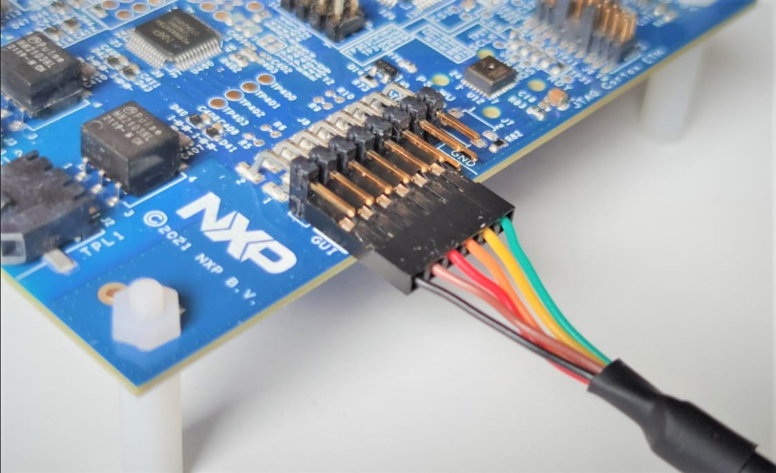
- Connect the provided USB-TTL cable to the RD-K344BMU (
J8), ensuring the black wire is on GND, yellow is on TX and orange is on RX - Configure the USB connection on FreeMASTER:
- In the FreeMASTER menu, click Tools and then select Connection Wizard...
- In the Connection Wizard window, click Next. Select Use direct connection to on-board USB port and click Next
- Select the correct USB serial port and select 115200 as baud-rate to probe and click Next
- Select Yes, use the detected port settings and start using FreeMASTER tool and click Finish
- In the FreeMASTER menu, click Go! or click Connect in the interface
- Programming the system:
- To install the development setup and start programming with the HVBMS reference design, refer to the HVBMS Software Installation Guide

Design Resources
References
In addition to our RD-HVBMSCTBUN: High Voltage Battery Management System, you may also want to visit:
Hardware pages:
- RD-K344BMU: HVBMS Battery Management Unit with S32K344 (BMU)
- RD33775ACNTEVB: HVBMS Cell Monitoring Unit (CMU)
- RD772BJBTPLEVB: HVBMS Battery Junction Box (BJB)
- BATT-14EXTENDER: Battery Emulator Extender
- BATT-14CEMULATOR: 14-Cell Battery Pack Emulator to Supply MC33771C BCC EVBs
Application pages: