Getting Started with the HVBMSCT800BUN Reference Design Bundle
Contents of this document
-
Out of the Box
-
Get Hardware
-
Configure Hardware
Sign in to save your progress. Don't have an account? Create one.
Purchase your RD-HVBMSCT800BUN
1. Out of the Box
The NXP analog product development boards provide an easy-to-use platform for evaluating NXP products. The boards support a range of analog, mixed-signal and power solutions. They incorporate monolithic integrated circuits and system-in-package devices that use proven high-volume technology. NXP products offer longer battery life, a smaller form factor, reduced component counts, lower cost, and improved performance in powering state-of-the-art systems.
This page will guide you through the process of setting up and using the HVBMSCT800BUN reference design bundle.
1.1 Kit Content and Packing List
The NXP analog product development boards provide an easy-to-use platform for evaluating NXP products. The boards support a range of analog, mixed-signal and power solutions. They incorporate monolithic integrated circuits and system-in-package devices that use proven high-volume technology. NXP products offer longer battery life, a smaller form factor, reduced component counts, lower cost, and improved performance in powering state-of-the-art systems.
This page will guide you through the process of setting up and using the HVBMSCT800BUN reference design bundle.
The RD-HVBMSCT800BUN bundle contains the following items:
- Battery Management Unit (BMU)
- 1 RD-K358BMU board
- 1 power supply (12 VDC, 5.0 A)
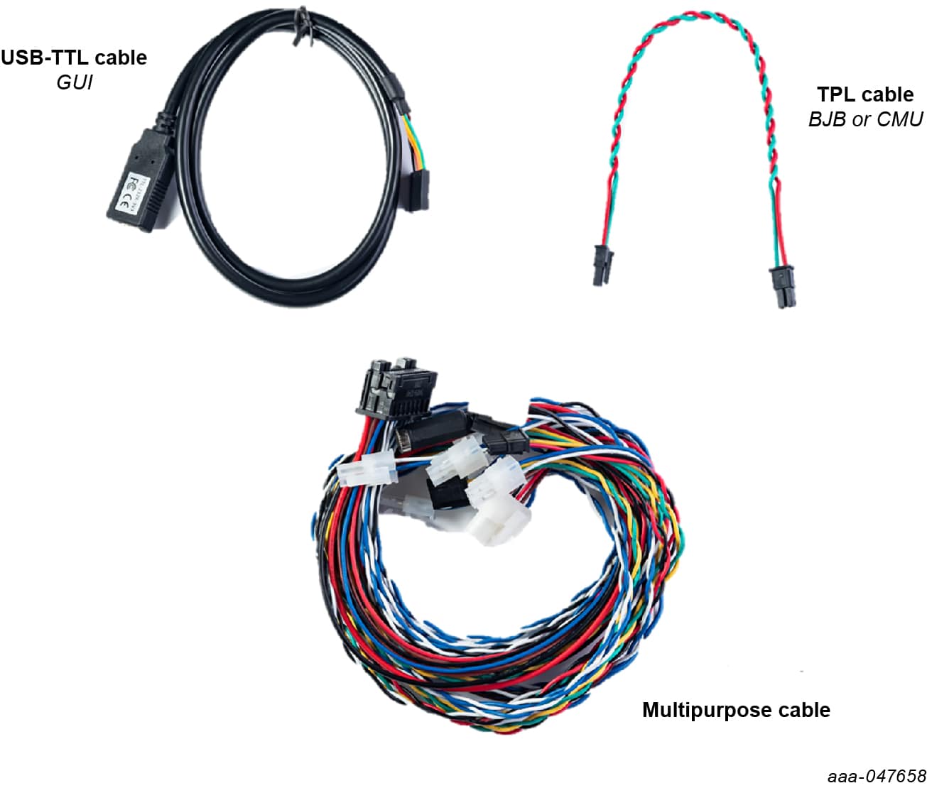
- 1 multipurpose cable
- 1 USB-TTL cable
- 1 Electrical Transport Protocol Link (ETPL) cable
- Cell Monitoring Unit (CMU)
- 1 RD33774CNT3EVB board
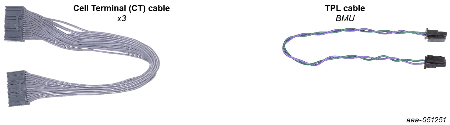
- 3 supply cables
- 1 ETPL cable
- Battery Junction Box (BJB)
- 1 RD772BJBTPL8EVB board
- 1 power cable
- 7 high-voltage measurement cables
- 1 pair of thermal sensor cable
- 1 chassis cable
- 1 ETPL cable
- 1 plexiglass cover
- Battery emulation kit
- 1 BATT-18EMULATOR board
- 1 power supply (5 VDC, 5.0 A)
1.2 Hardware Requirements
In addition to the kit contents, the following hardware is beneficial when working with this kit.
- A PC, to run the provided GUI and program the RD-K358BMU board
- A JTAG debugger to program the RD-K358BMU board. The recommended debugger is a PEmicro Multilink FX
2. Get Hardware
2.1 Board Features
- Scalability: high-voltage BMS chipset solutions for a wide range of applications to reduce development cost and enable faster time to market
- Safety: high system safety capability ensures proper operation of the battery at all times, protecting the passengers
- Precision: precise and synchronized measurements enable to leverage the full potential of the battery thus maximizing driving range
- Enablement: for each of the boards included in the enablement kit, hardware schematics, PCB layouts and Gerber files will be available on the NXP website for download (NDA required) and a system software development suite is available
2.2 Bundle Description
The RD-HVBMSCT800BUN is an ETPL-based high-voltage battery management system (HVBMS) reference design bundle for 800 V applications. This bundle has been designed for evaluation and development purposes. The RD-HVBMSCT800BUN is composed of a hardware kit and several software packages.
2.3 Bundle Components
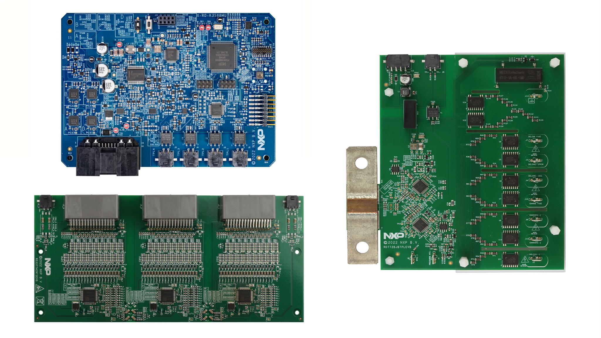
Battery Management Unit
The battery management unit (BMU) is the control part of the battery management system (BMS). The BMU processes the data, makes decisions, and commands the system.
The RD-K358BMU is the HVBMS reference design BMU for 800 V applications. This BMU kit includes a power supply and three cables to interface with other parts of the HVBMS.

Cell Monitoring Unit
The CMU is the cell-sensing part of the BMS. The CMU precisely monitors cell voltages and environmental temperatures to ensure safe battery operation. The CMU also enables fast cell-balancing.
The RD33774CNT3EVB is the HVBMS reference design CMU for ETPL-based architectures based on the MC33774A battery cell controller. This CMU kit includes four cables to interface with other parts of the HVBMS.

Battery Junction Box
The battery junction box (BJB) is the pack-level sensing part of the BMS. The BJB measures high voltages. This measurement allows monitoring connections of the contactors to the inverter and the charger. The BJB also precisely measures the system’s current, and monitors the battery to chassis isolation.
The RD772BJBTPL8EVB is the 800 V HVBMS reference design BJB for ETPL-based architectures. This BJB kit includes eleven cables to interface with other parts of the HVBMS.


Battery Emulation
To emulate cell voltages and temperatures, the RD-HVBMSCT800BUN contains a BATT-18EMULATOR battery emulator.

3. Configure Hardware
3.1 Configure the Hardware
To connect and power-up the system, complete the following steps:
-
Connections of the boards
- Unpack all boards and cables from the kit
- Connect the multipurpose cable to the RD-K358BMU (
J1) -
Connect the CMU
- Connect the first ETPL cable to the RD-K358BMU (
J2) and the RD33774CNT3EVB (J2_1) - Connect the second ETPL cable to the RD-K358BMU (
J3) and the RD33774CNT3EVB (J2_3) - Connect the three supply cables to the RD33774CNT3EVB (
J1_1,J1_2, andJ1_3) and the BATT-18EMULATOR (J4,J5, andJ6)
- Connect the first ETPL cable to the RD-K358BMU (
-
Connect the BJB
- Connect the ETPL cable between the RD-K358BMU (
J4) and the RD772BJBTPL8EVB (J9) - Connect the BJB supply cable between the RD-K358BMU (
J1, 4-pin connector, pins 11 to 14) and the RD772BJBTPL8EVB (J12)
- Connect the ETPL cable between the RD-K358BMU (
- Powering the boards
- Power the CMU by powering the BATT-18EMULATOR using the provided power supply (
J3) - Power the BMU by connecting the provided power supply to the multipurpose cable end
- Power the CMU by powering the BATT-18EMULATOR using the provided power supply (
- Monitoring the system using the HVBMS Start-up interface
- Open the HVBMS Start-up FreeMASTER project (HVBMS_800_StartUp_FreeMASTER.pmpx)
- Connect the provided USB-TTL cable to the RD-K358BMU (
J8), ensuring the black wire is on GND, yellow is on TX, and orange is on RX.
- In the FreeMASTER menu, click Tools and then Connection Wizard...
- In the Connection Wizard window:
- Click Next.
- Select Use direct connection to onboard USB port and click Next.
- Select the correct USB serial port and select 115200 as baud rate to probe and click Next.
- Select Yes, use the detected port settings and start using FreeMASTER tool and click Finish.
- In the FreeMASTER menu, click Go! or click Connect in the interface.
- Programming the system

To install the development setup and start programming with the HVBMS reference design, refer to the software section of the RD-HVBMSCT800BUN website.
Design Resources
Additional References
In addition to our MC33774, 18 Channel Li-Ion Battery Cell Controller IC ASIL D page, you may also want to visit:
- RD-K358BMU, S32K358 Battery Management Unit (BMU) for High Voltage Battery Management System (HVBMS) Reference Design Board
- RD772BJBTPL8EVB, HVBMS 800 V Battery Junction Box Using ETPL with MC33772C (BJB)
- RD33774ACNT3EVB, HVBMS Centralized Cell Monitoring Unit Using ETPL with MC33774A (CMU)
- BATT-18EMULATOR, 18-Cell Battery Pack Emulator to Supply MC33774A BCC EVBs