Getting Started with the FRDMGD3100HBIEVM
Contents of this document
-
Out of the Box
-
Plug It In
-
Configure Hardware
-
Get Software
Sign in to save your progress. Don't have an account? Create one.
Purchase your FRDMGD3100HBIEVM | GD3100 Evaluation Board
1. Out of the Box
The NXP analog product development boards provide an easy-to-use platform for evaluating NXP products. The boards support a range of analog, mixed-signal and power solutions. They incorporate monolithic integrated circuits and system-in-package devices that use proven high-volume technology. NXP products offer longer battery life, a smaller form factor, reduced component counts, lower cost and improved performance in powering state-of-the-art systems.
This page will guide you through learning about how to set up the FRDMGD3100HBIEVM board.
1.1 Kit Contents/Packing List
The FRDMGD3100HBIEVM contents include:
- Half-bridge gate driver board (FRDMGD3100HBIEVB)
- Logic translator board (KITGD3100TREVB) attached to FRDM-KL25Z
- A USB cable, type A male/type mini B male, 3 ft
- Quick Start Guide
1.2 Required Equipment
- Infineon IGBT FS820R08A6P2B HybridPACK™ Drive
-
DC Link capacitor compatible with IGBT
- SBE Power Ring 700A186, 500 µF, 500 V DC
- 50 mil jumpers for configuration
- 30 µH to 50 µH, high current air core inductor for double pulse testing
- HV power supply with protection shield and hearing protection
- 25 V, 1.0 A DC power supply
- Pulse generator
- TEK MSO 4054, 500 MHz, 2.5 GS/s, 4-channel oscilloscope
- Rogowski coil, PEM Model CWT Mini HF60R or CTW Mini HF30 (smaller diameter)
- Two isolated high voltage probes (CAL Test Electric CT2593-1, LeCroy AP030)
- Four low voltage probes
- Two digital voltmeters
2. Plug It In
2.1 Board Features
- Capability to connect to Infineon HybridPACK™ Drive IGBT module for half-bridge evaluations
- SPI communication, capable of daisy chain or normal
- Software configurable power and fail-safe controls
- Easy access power, ground and signal test points
- Easy to install and use SPIGen GUI for interfacing via SPI through PC. Software includes double pulse and short-circuit testing capability
-
DC Link bus voltage monitor on low-side driver via
AMUXINandAOUT
2.2 Board Description
The FRDMGD3100HBIEVM is a half-bridge evaluation board populated with two GD3100 single-channel IGBT gate drive devices. The board supports connection to a FRDM-KL25Z microcontroller for SPI communication and programming, through the use of a logic translator board.
The evaluation board is designed to connect to a single phase of an Infineon HybridPACK™ Drive IGBT for evaluation of the GD3100 performance and capabilities driving a power device. The board includes DESAT circuitry for short-circuit detection and implementation of GD3100 IGBT shutdown protection capabilities.
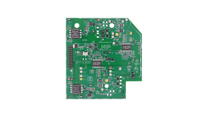
2.3 Board Image
The FRDMGD3100HBIEVM consists of 3 boards as shown in the final assembly below.

Overview of the FRDMGD3100HBIEVM evaluation board.

2.4 Kinetis KL25Z FRDM Board
The FRDM KL25Z is an ultra-low-cost development platform for Kinetis® L Series MCU built on Arm® Cortex®-M0+ processor.
2.5 Logic Translator Board
The FRDMGD3100HBIEVM includes a logic translator board, which provides simple isolation and is capable of level-shifting communication signals between the MCU and the GD3100 driver board. The driver board is exposed to high voltage and may require 3.3 V or 5.0 V logic, necessitating an interface board.

3. Configure Hardware
3.1 Configure Hardware
FRDMGD3100HBIEVM is connected to any phase of an Infineon Hybrid PACK Drive module with SBE DC Link capacitor. Double pulse and short-circuit testing can be conducted utilizing Windows-based PC with SPIGEN software.
Suggested equipment's needed for testing:
- Rogowski coil high current probe
- High voltage differential voltage probe
- High sample rate digital oscilloscope with probes
- DC Link capacitor
- Infineon Hybrid PACK Drive IGBT module
- Windows 7 based PC
- High voltage DC power supply for DC Link
- Low voltage DC power supply for VSUP/GD3100PWR
- +12 V DC gate drive board low voltage domain
- Voltmeter for monitoring high voltage DC Link supply
- Load coil for a double pulse and short-circuit type 2 testing

4. Get Software
4.1 Installing SPIGen on your Computer
Software for FRDMGD3100HBIEVM is distributed with the SPIGen GUI tool (available on NXP.com). Necessary firmware comes pre-installed on the FRDM-KL25Z with the kit.
The latest version of SPIGen supports the GD3100 and is designed to run on any Windows 10, Windows 8, or Windows 7-based operating system. To install the software, do the following:
- Go to SPI Generator (SPIGen) Software and click Download
- When the SPI Generator (SPIGen) software page appears, go to the Lab and Test Software section and click Download associated with the description of the selected environment. A wizard guides the user through the process
-
If instructed for the SPIGen wizard to create a shortcut, a SPIGen
icon appears on the desktop. By default, the SPIGen executable
file is installed at
C:\Program Files (x86)\SPIGen. Installing the device drivers overwrites any previous SPIGen installation and replaces it with a current version containing the GD3100 drivers. However, configuration files (.spi) from the previous version remain intact
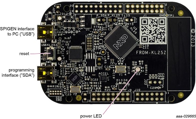
4.2 FRDM-KL25Z setup and interface image
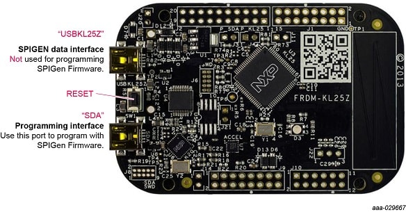
For additional information on microcode and FRDM-KL25Z configuration, refer to the user guide.
4.3 Using SPIGen with the GD3100 Gate Driver
In this video you will learn how to use the SPIGen software tool to configure and control the GD3100 evaluation board.
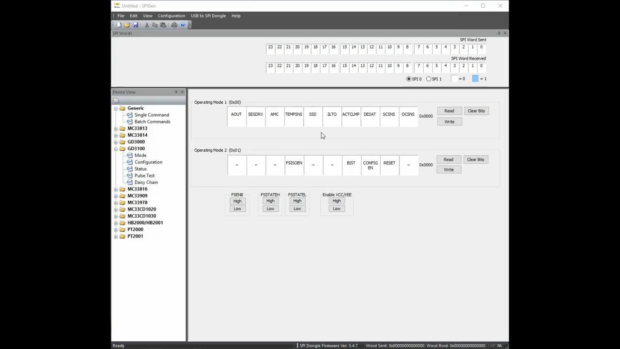
4.4 SPIGen GUI
The SPIGen graphical user interface is available from NXP.com as an evaluation tool demonstrating GD3100-specific functionality, configuration and fault reporting. SPIGen also includes basic capacity for the FRDMGD3100HBIEVM to control an IGBT, enabling double-pulse or short-circuit testing.

Design Resources
Additional Resources
Product Summary
The product summary page for GD3100 is located at Advanced High Voltage Isolated Gate Driver for IGBT and SiC MOSFETs.
Tool Summary
The overview section provides a description of the device, product features, list of the kit contents, list of (and links to) supported devices, list of (and links to) any related products and a Get Started section.
- Specifications: Board technical specifications and features
- Documentation and Software: Download current supporting documentation and software files
- Buy/Parametrics: Purchase the product and view the product parametric data and kit contents
- Support: Supporting information such as communities and partner information
After downloading files, review each file, including the user guide which includes setup instructions.
References
In addition to our GD3100: Advanced single-channel gate driver for Insulated Gate Bipolar Transistors (IGBTs) page you may also want to visit: