Getting Started with the EV-INVERTERHDBT IGBT Enablement Kit
Contents of this document
-
Get Started
-
Get Hardware
-
Configuring Hardware
-
Install Software Tools
Sign in to save your progress. Don't have an account? Create one.

Purchase your EV Power Inverter Control Reference Platform Gen 2
1. Get Started
The NXP analog product development boards provide an easy-to-use platform for evaluating NXP products. The boards support a range of analog, mixed-signal and power solutions. They incorporate monolithic integrated circuits and system-in-package devices that use proven high-volume technology. NXP products offer longer battery life, a smaller form factor, reduced component counts, lower cost and improved performance in powering state-of-the-art systems.
This page will guide you through the process of setting up and using the EV-INVERTERHDBT enablement kit.
1.1 Kit Contents and Packing List
The EV-INVERTERHDBT kit contents include:
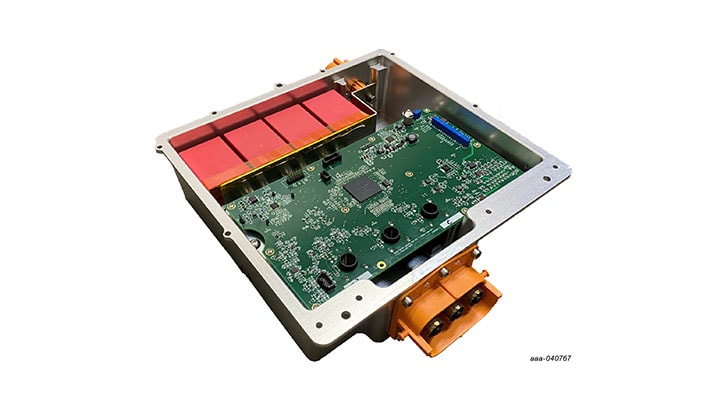
- MCU control board (EV-CONTROLEVMHD)
- Driver control board (EV-POWEREVBHDBT)
- 3-phase connection bus bars
- Software license
- Quick start guide
1.2 Additional Hardware
In order to use the EV-INVERTERHDBT IGBT enablement kit, customers must provide some additional hardware beyond what is contained in the kit. The amount of additional hardware required depends on whether the customer is using the Vepco PIM or is designing their own EV Inverter platform.
All customers (Vepco PIM users included) must provide the following items:
- Low voltage DC power supply: A 12 VDC power supply for the inverter
- High-voltage DC power supply: Up to 500 VDC, 400 A (or similar) for the motor
- Kvaser Leaf Light HS v2 USB-CAN interface or comparable USB-CAN interface adapter (available here )
- PEMicro Multilink debug probe: To connect the EV-CONTROLEVMHD board to the PC-based GUI (available here )
- Motor: A 3-phase permanent magnet synchronous motor
- High-voltage cabling (2-wire): For high-voltage connections from high-voltage DC power supply into the PIM
- High-voltage cabling (3-wire): For high-voltage connections from the PIM to the motor
- Low-voltage cabling: For low-voltage connections from the 12 VDC power supply to the PIM
In addition to the required equipment listed above, customers who choose to design their own inverter platform must also provide the following:
- P6 footprint IGBT module: P6 footprint IGBT module like onsemi VE-TrackTM, Infineon HybridPACKTM are compatible with NXP EV-INVERTERHDBT enablement kit
- IGBT HybridPACK module: Available for purchase here from StarPower Europe AG by authorized customers of the NXP EV-INVERTERHDBT enablement kit
- Cooling plate or water jacket for SiC or IGBT P6 footprint module: The cooling plate serves as the cooling structure interface for the SiC or IGBT module
- Bus bar: Used to connect the DC link capacitors to the IGBT module and to provide links to the DC high-voltage/high current power supply
- DC link capacitor: Four KEMET C4AQIEW6100A3BJ 100 μF 800 VDC RAD capacitors (available here ) connected in parallel are used for inverter baseline performance measurements. The selected capacitors must be compatible with the IGBT or SiC module listed above and its intended operating voltages
- 23-position signal connector (optional): Ampseal (PN 770680-1) connector (available here ) to connect the PIM to a 3-Phase motor
- High-voltage shielded cable (2-wire): Used to connect the 23-position signal connector to the motor resolver connections excitation signals
- Low-voltage shielded cable (21-wire): Used to connect the 23-position signal connector to the motor resolver sense signals, CAN, signals, etc
- 40-pin cable: 40-pin flat ribbon cable with two male connectors to connect the EV- CONTROLEVMHD MCU control board to the EV-POWEREVBHDBT driver control board
- Board stand-offs: To provide mechanical support for the components
1.3 Windows PC Workstation
This reference platform requires a Windows PC workstation. Meeting these minimum specifications should produce great results when working with this reference platform.
- Windows 10, 8 or 7 compatible PC with two available USB ports
1.4 Software
The software listed below must be installed prior to working with this reference design. All listed software is available on an NXP secured site. To gain access to the secured site, use the registration code provided in the hardware shipment. The software bundle includes the actual application software that runs on the EV-INVERTERHDBT IGBT enablement kit. Customers who purchase the EV-INVERTERHDBT enablement kit receive instructions on how to download the software.
- S32 Design Studio IDE V2.1 for Power Architecture
- Automotive Math and Motor Control Library (AMMCL)
- FreeMASTER 3.0 runtime debugging tool
- Motor Control Application Tuning (MCAT)
- Example code, GD3160 Device Driver notes and GD3160 Device Driver Reference notes
2. Get Hardware
2.1 Board Features
Benefits:
- Increases speed of development
- Full platform solution
- Provides functional safety options
- Optimizes performance
Featured Products
- GD3160 isolated SiC MOSFET or IGBT ASIL D gate driver
- MPC5775E advanced motor control ASIL D MCU
- FS65XX robust ASIL D SBC
- TJA1051 redundant CAN bus interface
- TJA1100 IEEE 100BASE-T1 compliant Automotive Ethernet PHY Transceiver interface (optional)
- Capability to connect to a P6 footprint module for three-phase evaluations
2.2 Board Description
The EV-INVERTERHDBT is a reference design IGBT enablement kit containing NXP content to develop an EV three-phase traction motor inverter. The system is designed to drive an IGBT with equivalent P6 footprint HybridPACK pin out and form factor. This kit includes two PCBs, 3-phase bus bars and basic configuration and enablement software. PCB board layout, schematics and Gerber files are available on an NXP secured website. To gain access to the secured site, use the registration code provided in the hardware shipment.
Customers must obtain the additional inverter components. These components include the IGBT module, link capacitor, bus bar, cooling plate, mounting hardware, etc. Customers can select their own components when designing and assembling a complete PIM to work with the NXP EV-CONTROLEVMHD and EV-POWEREVBHDBT boards. As an alternative, a complete pre-assembled reference PIM platform is available through NXP partner Vepco Technologies.


3. Configuring Hardware
The procedure for assembling an inverter platform that uses the EV-INVERTERHDBT IGBT enablement kit differs depending on whether the Vepco PIM is employed or whether the customer has chosen to configure their own platform. The following sections cover both procedures.
3.1 Assemble the Hardware (Vepco Procedure)
The assembly instructions in this section apply to users who have elected to use the Vepco PIM.
The following hardware is required for this procedure:
- Vepco Power Inverter Module (PIM)
- High-voltage cabling for inverter supply (2-wire)
- High-voltage cabling for motor connection (3-wire)
- 12 V power supply (inverter)
- High-voltage power supply (motor)
- Motor
- PEMicro Multilink debugger probe
- Kvaser Leaf Light v2 USB – CAN interface adapter
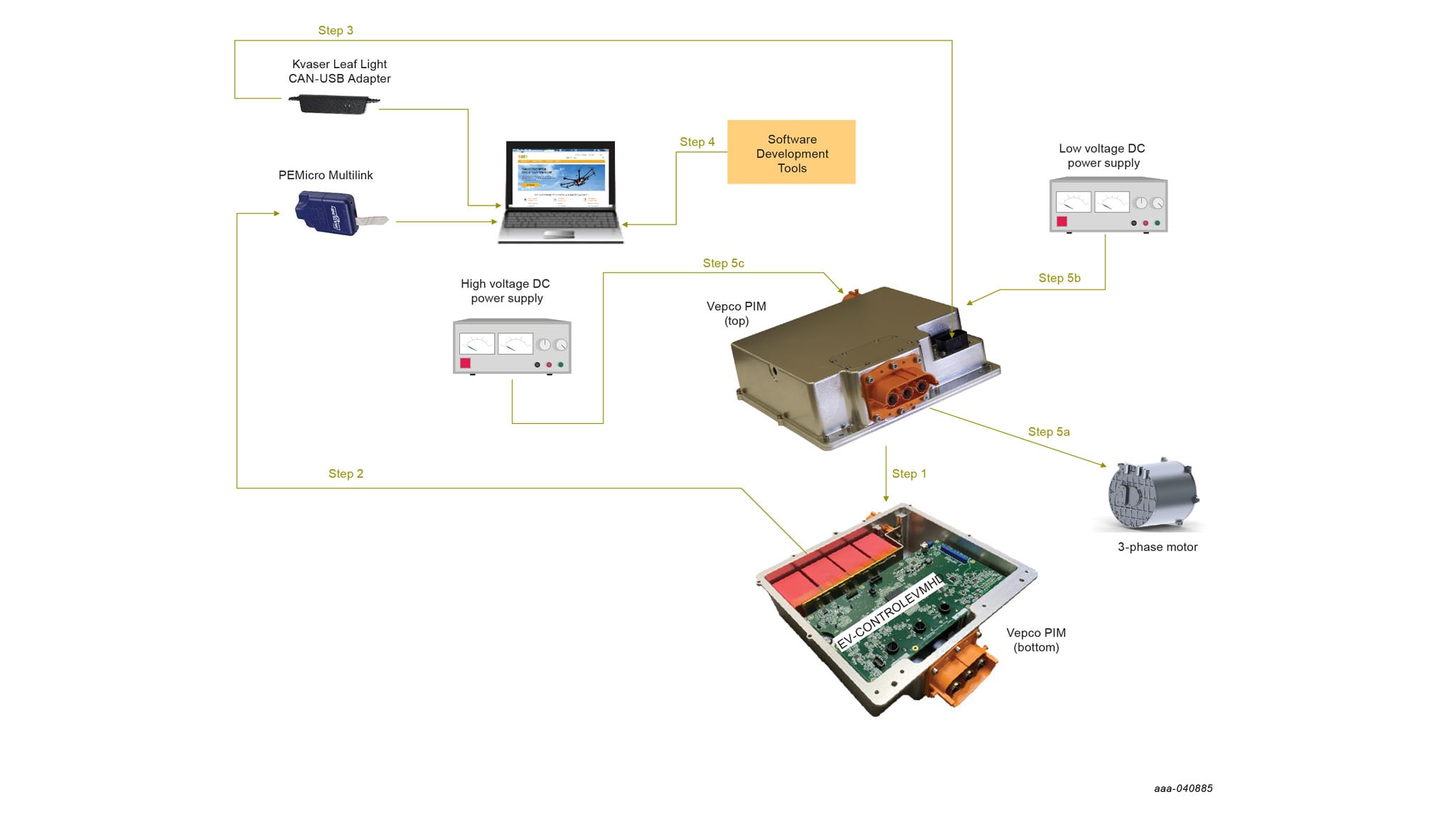
- Turn the Vepco PIM upside down and remove the bottom plate. This exposes the EV- CONTROLEVMHD board mounted inside the unit.
- Connect the 14-pin PEMicro Multilink debugger header to connector P1 on the EV- CONTROLEVMHD with the pin 1 marks aligned. Connect a USB cable from the PEMicro Multilink to the host PC. Both LED lights on the PEmicro Multilink should be on, indicating the CAN bus is live and ready to communicate. For information on installing the PEMicro software and debugging with the PEMicro probe, see PEMicro documentation.
- Route the Kvaser Leaf Light USB-CAN Interface Adapter from the 23-pin connector on the bottom of the EV-CONTROLEVMHD board to a USB port on the Windows PC.
- Install the software development tools.
-
Follow the instructions in the Vepco PIM documentation to make the following connections:
- 3-phase motor
- Low-voltage DC power supply
- High-voltage DC power supply. Warning: HIGH DC VOLTAGES CAN BE FATAL. Use extreme caution
Lethal voltage and fire ignition hazard
The non-insulated high voltages that are present when operating this product, constitute a risk of electric shock, personal injury, death and/ or ignition of fire. This product is intended for evaluation purposes only. It shall be operated in a designated test area by personnel qualified according to local requirements and labor laws to work with non- insulated mains voltages and high-voltage circuits. This product shall never be operated unattended.
3.2 Assemble the Hardware (Non-Vepco Procedure)
The following assembly instructions apply to users who have elected to design their own inverter control platform instead of using the Vepco module. The instructions cover electrical connectivity only. The customer is responsible for assembling the physical structures (bus bar, mounting hardware, etc.) required to support and connect the components in their platform.
- EV-INVERTERHDBT IGBT Enablement Kit
- P6 footprint IGBT module
- Cooling plate
- A bus bar compatible with a P6 footprint IGBT module
- DC link capacitors
- High-voltage cabling for inverter supply (2-wire)
- High-voltage cabling for motor connection (3-wire)
- High-voltage shielded cable (2-wire) for motor resolver connections
- Low-voltage shielded cable (21-wire) for motor resolver connections
- 23-position Ampseal signal connector (optional)
- 12 V power supply (inverter)
- High-voltage power supply (motor)
- 40-pin flat ribbon cable with one male and one female connector (optional)
- Board stand-offs -0.5 in (optional)
- Motor
- PEMicro Multilink debugger probe
- Kvaser Leaf Light v2 USB – CAN interface adapter

- Attach the IGBT module to the cooling plate.
- Attach the DC link capacitors to the bus bar.
- Connect the three positive power connectors on the IGBT module to the corresponding connectors on the bus bar. Connect the three negative power connectors on the IGBT module to the corresponding connectors on the bus bar.
- Connect output phase bus bars to the three output connectors on the IGBT module with the screws provided in the kit. Then, route each bus bar through one of the three motor phase current sensors(U21, U22, U23) on the EV-CONTROLEVMHD board.
- Connect the 3-phase motor by drawing high voltage cables from the three output phase bus bars that were routed through the current sensors in the previous step. Make sure that the U, V and W connections match. Secure the connection with the screws provided in the kit and ensure that the plastic caps are placed on top of the screws.
-
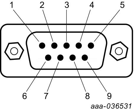
Connect the motor resolver to the 23-pin connector on the EV-CONTROLEVMHD board (refer to EV-CONTROLEVMHD board schematics). The connections are made as follows:
- Using the two-wire high-power shielded cable, connect pin 14 and pin 21 (resolver excitation signals) on the 23-pin connector to the corresponding connections on the motor. Connect the shield ground to pin 6 on the 23-pin connector
- Using the low-power cable, connect pins 8, 15, 22, and 23 (resolver sense signals) on the 23-pin connector to the corresponding connections on the motor. Connect the shield ground to pin 7 on the 23-pin connector
- Using the low-power cable, make all remaining connections (CANH, CANL, etc.)
- Connect the EXT_DGND to 12 V GND
-
Connect the two enablement kit boards. The connection can be made using two different methods:
- Method A: Mount the EV-CONTROLEVMHD board on top of the EV- POWEREVBHDBT board by directly connecting the 40-pin connectors (J1 and P1) and the +12 supply connectors (P6 and P2). Make sure that the pins on the lower board are inserted into the connectors on the upper board. Use stand-offs to provide structural support between the two boards. Notice that connecting the boards in this fashion blocks access to the test points and components on the top of the EV- POWEREVBHDBT board
- Method B: Connect the two boards with cables. To do so, connect a 40-pin ribbon cable between connector J1 on the EV-CONTROLEVMHDBT board and connector P1 on the EV-POWEREVBHDBT board. In this configuration, the EV-POWEREVBHDBT board must be powered independently from the EV- CONTROLEVMHD board (see step 9)
- Connect the EV-POWEREVBHDBT board to the IGBT module. This is best done by aligning the pins on the surface of the IGBT module with the IGBT module connectors on the bottom of the EV-POWEREVBHDBT board and mounting the two units together. Alternatively, each of the pins on the PC module can be wired to the corresponding connector on the EV-POWEREVBHDBT board.
- Connect the low-voltage DC power supply (12 V) to connector P6 on the EV- CONTROLEVMHD board. If Method B in Step 6 was used to connect the EV- CONTROLEVMHD board to the EV-POWEREVBHDBT board, an additional connection must be made from the low-voltage DC power supply to the +12 Supply connector (P2) on the EV-POWEREVBHDBT board. When the two boards are mounted, as in Method A, Step 7, the EV-POWEREVBHDBT draws power directly through the +12 Supply connector on the EV-CONTROLEVMHD board.
- Using the 2-wire high-voltage cable, connect the positive connector on the high- voltage/high-current DC supply to the positive DC link capacitor connectors on bus bar. Then connect the negative connector on the high-voltage/high current DC supply to the negative DC link capacitor connectors on the bus bar. Warning: HIGH DC VOLTAGES CAN BE FATAL. Use extreme caution. Before applying high voltage (>300 V) to the DC connection, use a current limited (1.0 A) power supply and apply 15 V to 30 V to the DC to make sure that there is no excessive leakage current.
Lethal voltage and fire ignition hazard
The non-insulated high voltages that are present when operating this product, constitute a risk of electric shock, personal injury, death and/ or ignition of fire. This product is intended for evaluation purposes only. It shall be operated in a designated test area by personnel qualified according to local requirements and labor laws to work with non-insulated mains voltages and high-voltage circuits. This product shall never be operated unattended.
- Connect the 14-pin PEMicro Multilink debugger header to connector P4 on the EV-CONTROLEVMHD with the pin 1 marks aligned. Connect a USB cable from the PEMicro Multilink to the host PC. Both LED lights on the PEmicro Multilink should be on, indicating that the JTAG bus is live and ready to communicate. For information on installing the PEMicro software and debugging with the PEMicro probe, see PEMicro documentation.
- Attach the Kvaser Leaf Light USB-CAN Interface Adapter to the 23-pin connector on the bottom of the EV-CONTROLEVMHD board and a USB port on Windows PC.
- Install the software development tools.
4. Install Software Tools
4.1 S32S Design Studio IDE for Power Architecture
The S32 Design Studio IDE is a complimentary integrated development environment for Automotive and Ultra-Reliable MCUs that enable editing, compiling and debugging of designs.
- Go to S32DS-PA and click User Guide.
- Follow the instructions within the S32 Design Studio for Power Architecture 2.1 installation guide.
- Run the S32 Design Studio by clicking the S32 Design Studio for Power Architecture V2.1 icon.
-
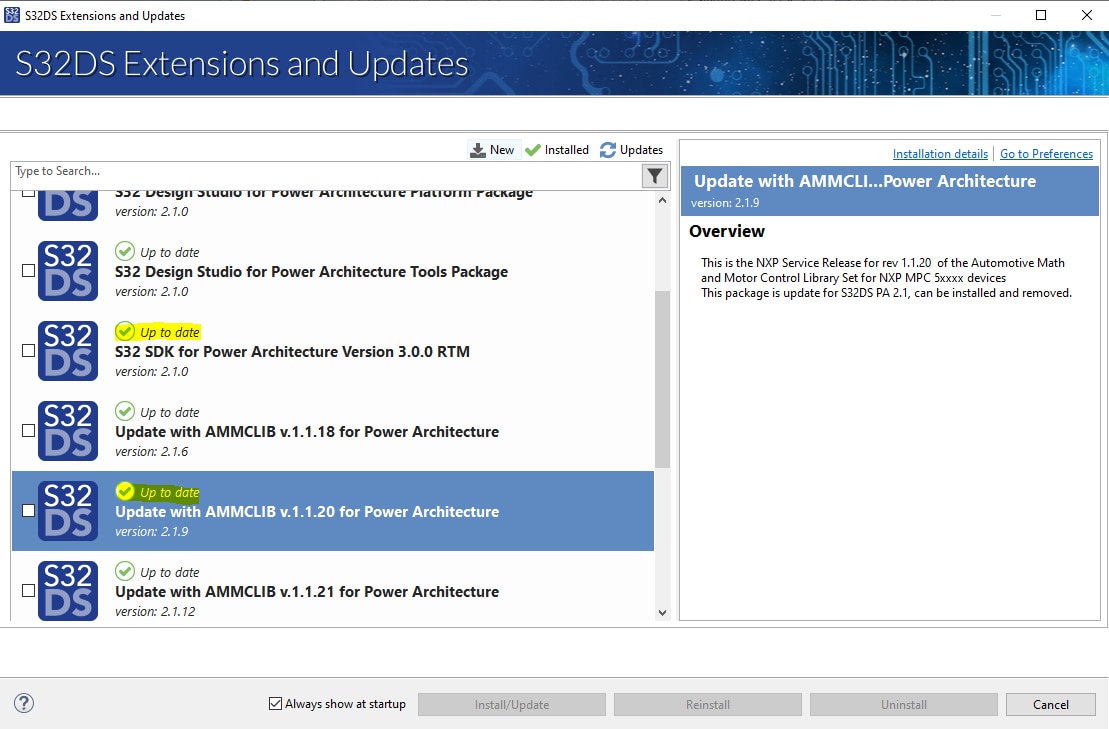
Before flashing the device, verify that the updates have been installed on the S32 design studio for S32_SDK_S32PA_RTM_3.0.0 and AMMCLIB_1.1.20. To do so, go to
Help
and check for S32DS extensions and updates. It should be up to date with S32 SDK for Power architecture version 3.0.0 RTM and update with AMMCLIB v.1.1.20 for power
architecture.
-
Click Run > Flash from file...

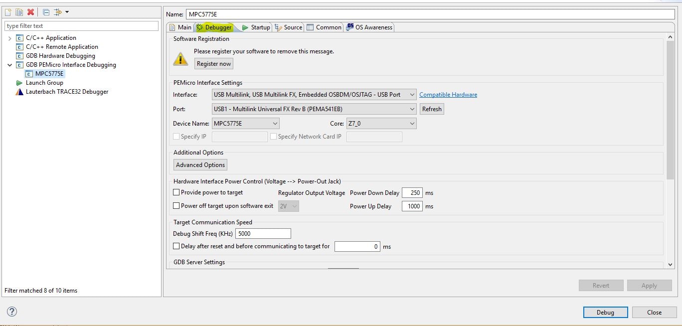
- Double-click the GDB PEmicro Interface Debugging icon.
-
Change the name of the new configuration to MPC5775E.
-
Click the Debugger tab.

- Click the Device Name drop-down menu and select MPC5775E.
- Click Apply.
- Flash the .elf file.
4.2 Install the USB – CAN Interface Adapter
- Browse to Kvaser Downloads
-
Download the latest Kvaser drivers for Windows and install them. The driver page is shown below

-
Connect the USB-CAN interface adapter to a USB port on the computer

Design Resources
Board Information
Refer to UM11676, EV-INVERTERHDBT IGBT enablement kit found on an NXP secured site for complete information on the featured components and board configuration.
Additional References
In addition to our IGBT EV Power Inverter Control Platform page, you may also want to visit:
Product pages:
- MPC5775B and MPC5775E microcontrollers for Battery Management Systems (BMS) and Inverter applications
- GD3160: Advanced Single-Channel High-Voltage Isolated Automotive Gate Driver for SiC MOSFETs/IGBTs
- FS6500: Grade 1 and Grade 0 safety power system basis chip with CAN flexible data transceiver
- TJA1051: High-Speed CAN Transceiver
- TJA1100HN: IEEE 100BASE-T1 Compliant Automotive Ethernet PHY Transceiver
Application pages:
Hardware pages:
Software pages: