Product Longevity
Participating products are available for a minimum of 10 years. Designated participating products developed for the automotive, telecom and medical segments are available for a minimum of 15 years.
Sign in for a personalized NXP experience.
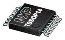
The TJA1083G FlexRay™ node transceiver is compliant with the FlexRay Electrical Physical Layer specification ISO 17458-4:2013. The TJA1083G is a Clamp 15 transceiver, optimized for applications that are switched off by the ignition key. It is primarily intended for communication systems operating at between 2.5 Mbit/s and 10 Mbit/s and provides an advanced interface between the protocol controller and the physical bus in a FlexRay network.


Participating products are available for a minimum of 10 years. Designated participating products developed for the automotive, telecom and medical segments are available for a minimum of 15 years.

FlexRay Transceiver

FlexRay™ Node Transceiver - Clamp 30
1 result
Include 0 NRND
Part | Order | CAD Model | Status | Features | Additional Features - Analog | Supply Voltage [Min to Max] (V) | Data Rate [min] kbps | Data Rate [max] kbps | Flexray | Voltage on bus pins [Min-Max] (V) | VESD HBM on bus pins (+/- kV) | VESD IEC on bus pins (+/- kV) | Junction Temperature (Min) (℃) | Junction Temperature (Max) (℃) | Protection | Wake-Up Pin | Product Application | Package Type |
|---|---|---|---|---|---|---|---|---|---|---|---|---|---|---|---|---|---|---|
Active | FlexRay EPL v3.0.1 | Standby Mode | 4.75 to 5.25 | 2500.0 | 10000.0 | 1 | -60 to 60 | -8 to 8 | -6 to 6 | -40 | 150 | overtemperature, undervoltage detection | Y | Automotive | TSSOP14 |
Quick reference to our documentation types.
2 documents
Compact List
There are no results for this selection.
Sign in to access authorized secure files. Learn more about secure access rights.
Please wait while your secure files are loading.
2 documents
Compact List

Receive the full breakdown. See the product footprint and more in the eCad file.
There are no recently viewed products to display.

Help us improve your experience on our site. We invite you to take our five-question survey.