Getting Started with the UCANS32K1SCT Evaluation Board
Contents of this document
-
Out of the Box
-
Get the Hardware
-
Configure Hardware
Sign in to save your progress. Don't have an account? Create one.
Purchase your UCANS32K1SCT Evaluation Board
1. Out of the Box
1.1 Out of the Box
The NXP analog product development boards provide an easy-to-use platform for evaluating NXP products. The boards support a range of analog, mixed-signal and power solutions. They incorporate monolithic integrated circuits and system-in-package devices that use proven high-volume technology. NXP products offer longer battery life, a smaller form factor, reduced component counts, lower cost and improved performance in powering state-of-the-art systems.
This page will guide you through the process of setting up and using the UCANS32K1SCT demo kit.
1.2 Kit Content and Packing List
The UCANS32K1SCT contents include:
- Assembled and tested demo kit and accessories in antistatic bag
- Quick Start Guide
1.3 Additional Hardware
- Micro USB cable (required for powering the demo kit)
- CAN FD analyzer (recommended), for example, the CAN FD adapter PCAN-USB FD
- PC with Windows OS, for example, Win 7 or later (optional)
1.5 Static Handling Requirements
This device is sensitive to ElectroStatic Discharge (ESD). Therefore care should be taken during transport and handling. You must use a ground strap or touch the PC case or other grounded source before unpacking or handling the hardware.
Get the Hardware
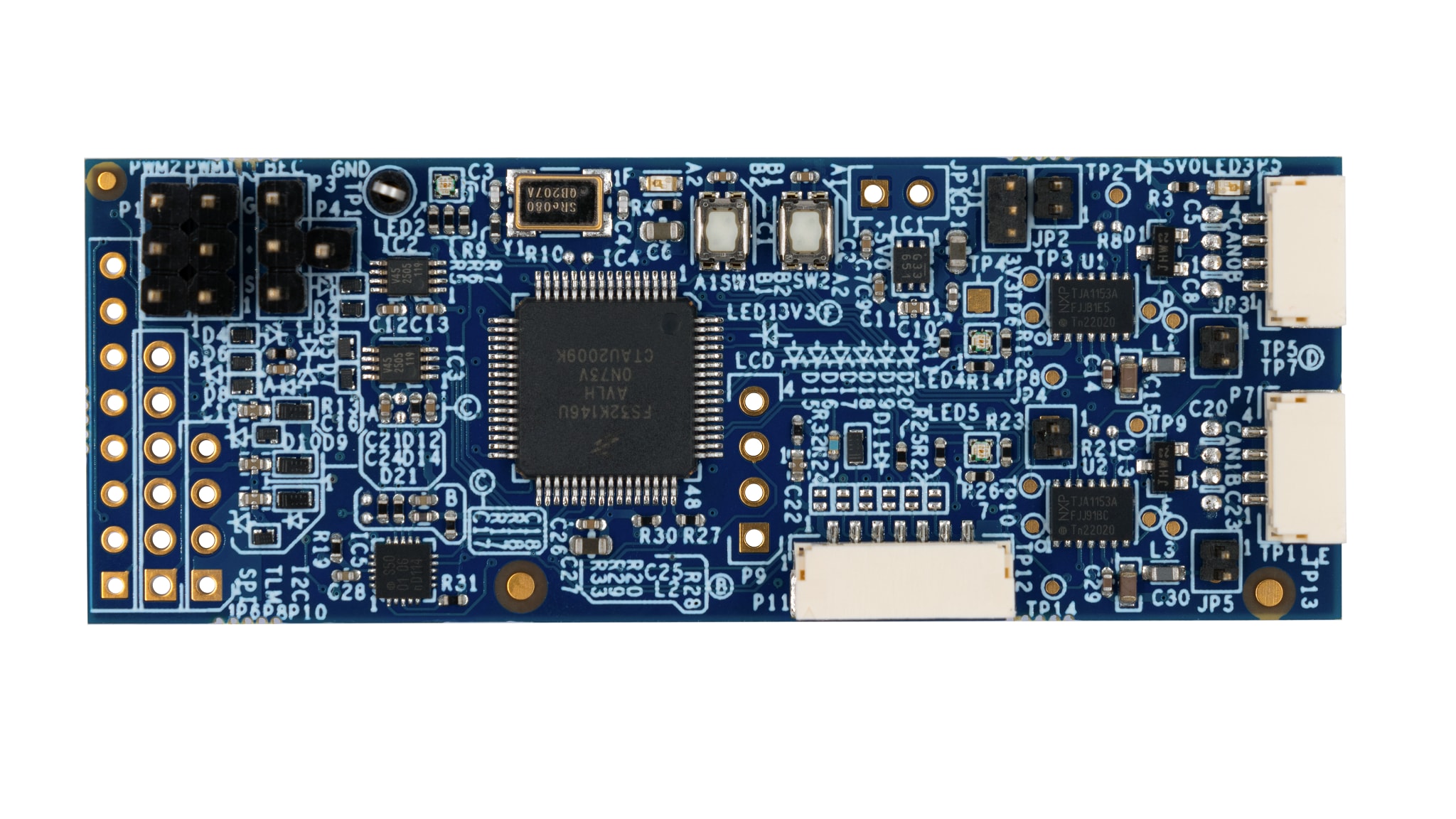
2.1 Board Features
- Two CAN FD channels equipped with TJA1153A (HVSON14 package)
- 5.0 V supply voltage via CAN connectors or on the board
- 3.3 V regulator on the board to generate transceiver VIO and MCU supply. This regulator is controlled by the INH pins of TJA1153A
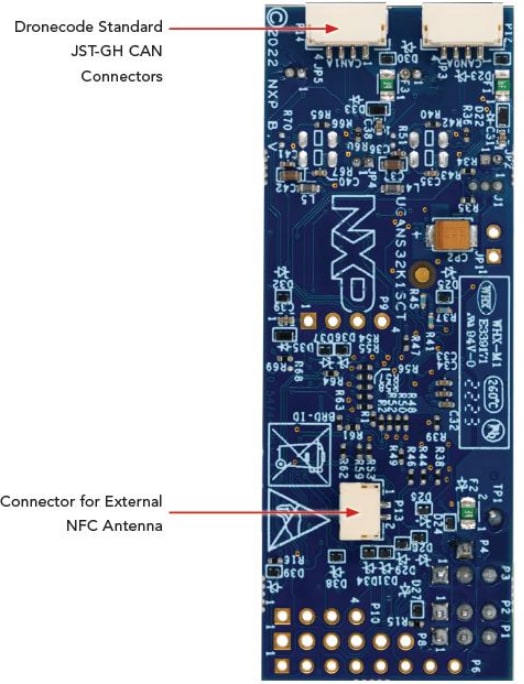
2.2 Board Description
The board consists of two nodes represented by two CAN FD channels equipped with Secure CAN transceivers TJA1153A. The onboard RGB LEDs provide direct feedback where LED2 indicates the chosen scenario and its status while LED4 and LED5 indicate the status of CAN FD Node A and B respectively.
As an alternative to the onboard user button, it is recommended to control the demo via console using the UART interface of the board.
It is also recommended to connect a CAN FD analyzer through the unused CAN channel interface of the board to more intuitively observe various information being interacted on the CAN bus, including normal CAN (FD) messages, as well as the behavior of the Secure CAN, etc.

Configure Hardware
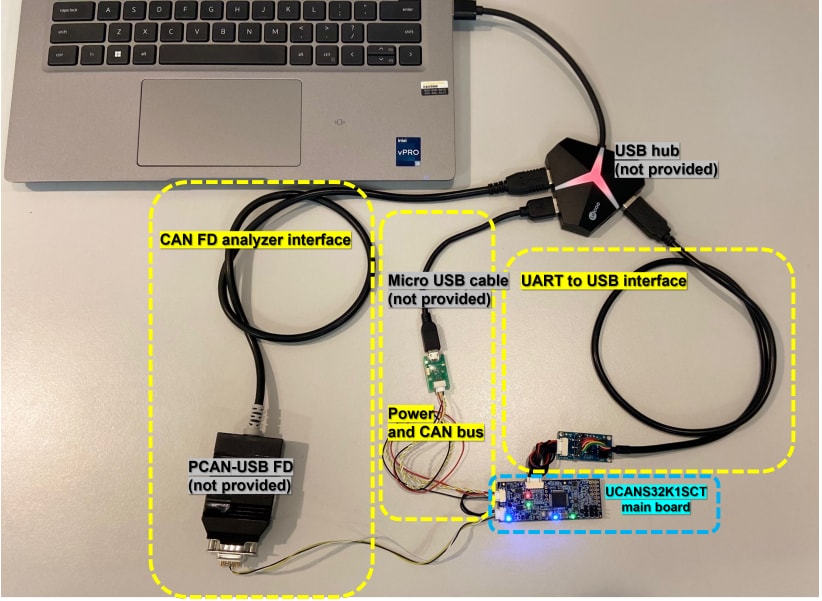
3.1 Configure Hardware
The following figure is a complete overview of the UCANS32K1SCT demo kit. It contains four main components groups, namely:
- UCANS32K1SCT main board
- Peripherals for USB power and CAN bus (Micro USB cable is not provided)
- Peripherals for UART to USB, to PC
- Peripherals for CAN FD analyzer interface (CAN FD analyzer is not provided)
Design Resources
Additional References
In addition to our TJA1153, Secure HS-CAN Transceiver with Sleep Mode page, you may also want to visit: