Getting Started with the S32V234-EVB2
Contents of this document
-
Out of the Box
Sign in to save your progress. Don't have an account? Create one.

Purchase your S32V2 Vision and Sensor Fusion Evaluation System
1. Out of the Box
1.1 Powering You System
Your S32V234-EVB2 uses a 12 V barrel jack power supply or wire-ended jack.
Do not use the two different jacks at the same time. Doing so will likely damage the board.
The 12 V hot goes to PIN 1 of the barrel jack or wire-end plug. See rear of board for pin marking.
The dual position SW (SW9) controls power flow and the red TP93 is available for measuring
12 V prior to main power SW (SW9).

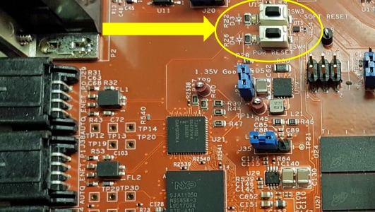
1.2 Reset Options
Your S32V234-EVB2 evaluation system provides a POR RESET and SOFT RESET buttons:
- Pressing POR RESET pulls active low
EXT_PORsignal on S32V234 chip to GND - Pressing SOFT RESET pulls active low
RESETsignal on S32V234 chip to GND
1.3 Serial Communications Within the Evaluation System
Your S32V234-EVB2 has an FTDI chip to convert UART signals to USB friendly format for connecting to the host PC.

The UART 0 is a default serial output for
Linux Board Support Package for S32V boot images.
Default comms rate is 115200 baud with 8 data bits, 1 stop bit, no parity.
For Windows, you can use Tera Term or PuTTY to communicate with the board.
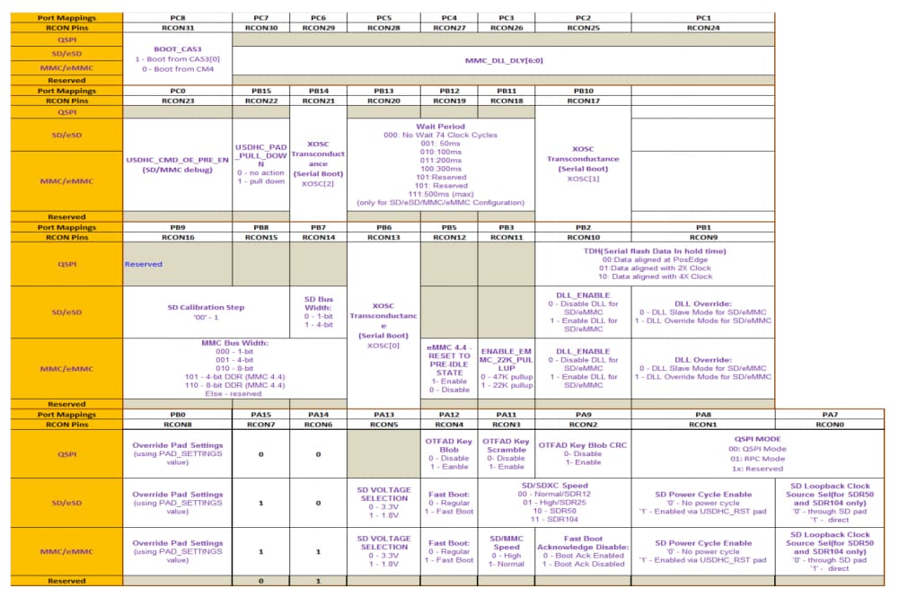
1.4 Boot Configurations
Your S32V234-EVB2 evaluation system has three boot modes:
- Serial download: Allows an external tool to use CAN or UART to download code into RAM and start execution. Code must be redownloaded on every reset in this mode. Uses a baud rate of 48 kbps
- Boot from fuses: Configures device to boot according to the internal eFuse values programmed at factory. This is generally not used for evaluation boards due to lack of custom fuse programming
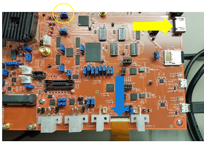
- Boot from RCONs: The most common configuration, allows customization of the boot configuration via four 8-bit DIP switches on EVB2 (circled in picture)
The modes are selected by
BOOT_MODE0/1 signals controlled by the
J40 (Boot_Mode[0]) and J42 (Boot_Mode[1]), jumpers
and are read at reset. By default, the S32V234-EVB2 is configured to use the
boot from RCONs mode.
By default, the board boots from the RCON switches, which allows you to choose the boot core and SD card modes for advanced use cases.

The S32V234-EVB2 can be configured to boot from the SD card, EMMC or QSPI by
using jumpers
J48 and J49. Booting from the SD card is the factory
default setting:
-
Boot from SD:
J48= 1&2,J49= 1&2 andSW8= 0x80 -
Boot from EMMC:
J48= 1&2,J49= 2&3 andSW8= 0xC0 - Boot from QSPI:
J48= 2&3 andSW8= 0x01
1.5 Display
Your S32V234-EVB2 evaluation system has two display options: TFT or HDMI.
- HDMI: Jumper
J36set to 1&2 - LVDS: Jumper
J36set to 2&3
Turn off the power to the board before changing jumpers or switches.
1.6 Camera Inputs
Your S32V234-EVB2 evaluation system offers two MIPI camera inputs and two VIU (parallel) inputs. NXP and its distributors sell MIPI cameras designed for use with this board.
You can also add 5 V/12 V external power. See the schematics for pinout.
Turn off the power to the board before changing jumpers or switches.

-
Configuring Optional Voltage:
-
For 5 V on cameras 0/1, set jumpers
J7andJ5to 2&3 respectively -
For 12 V, set jumpers
J7andJ5to 1&2 respectively
-
For 5 V on cameras 0/1, set jumpers
-
Enabling/Disabling Optional Voltage:
-
To enable for cameras 0/1, set jumpers
J6andJ4to 1&2 respectively -
To disable, set
J6andJ4to 2&3 respectively
-
To enable for cameras 0/1, set jumpers
1.7 Camera Configurations
By default, jumpers J6 and J4 should be set to 2&3
to keep optional voltage disabled.
This configuration is suitable for most MIPI cameras that do not require additional voltage supply. It is also the safest configuration when using a new camera.
Two NXP-endorsed MIPI cameras use this configuration: the OV10640 module and the Sony IMX224 camera.

Another NXP-endorsed camera module is the OV10635/10640 with MAXIM 9271 Serializer, paired with the MAXIM 9286 Deserializer. This camera set requires the optional 12 V to be enabled.

- To prepare to use the MAX9271/86 Ser/Des setup, first ensure power is off and unplugged from the board
-
Then, choose between MIPI 0 or 1 and configure only
J7orJ5respectively to 1&2 to select 12 V -
Set jumpers
J6orJ4to 1&2 to enable optional voltage -
Confirm that the MAX9286 deserializer board is configured to use board power
by setting its jumper
JU4to the position shown (For Rev A deserializer boards)
Once all of these are set and cameras are connected, power can be turned on. Be sure to power off before removing cameras or components.
| ACTION | Camera on MPI0 | Camera on MPI1 |
|---|---|---|
| Set to 12 V | J7 = 1&2 |
J5 = 1&2 |
| Enable voltage | J6 = 1&2 |
J4 = 1&2 |
| Disable voltage | J6 = 2&3 |
J4 = 2&3 |
Check our S32V MIPI cameras and de-serializer.