Getting Started with the S32M27XEVB Evaluation Board
Contents of this document
-
Out of the Box
-
Get Software
-
Plug It In
-
Build
Sign in to save your progress. Don't have an account? Create one.

Purchase your S32M27x Evaluation Board
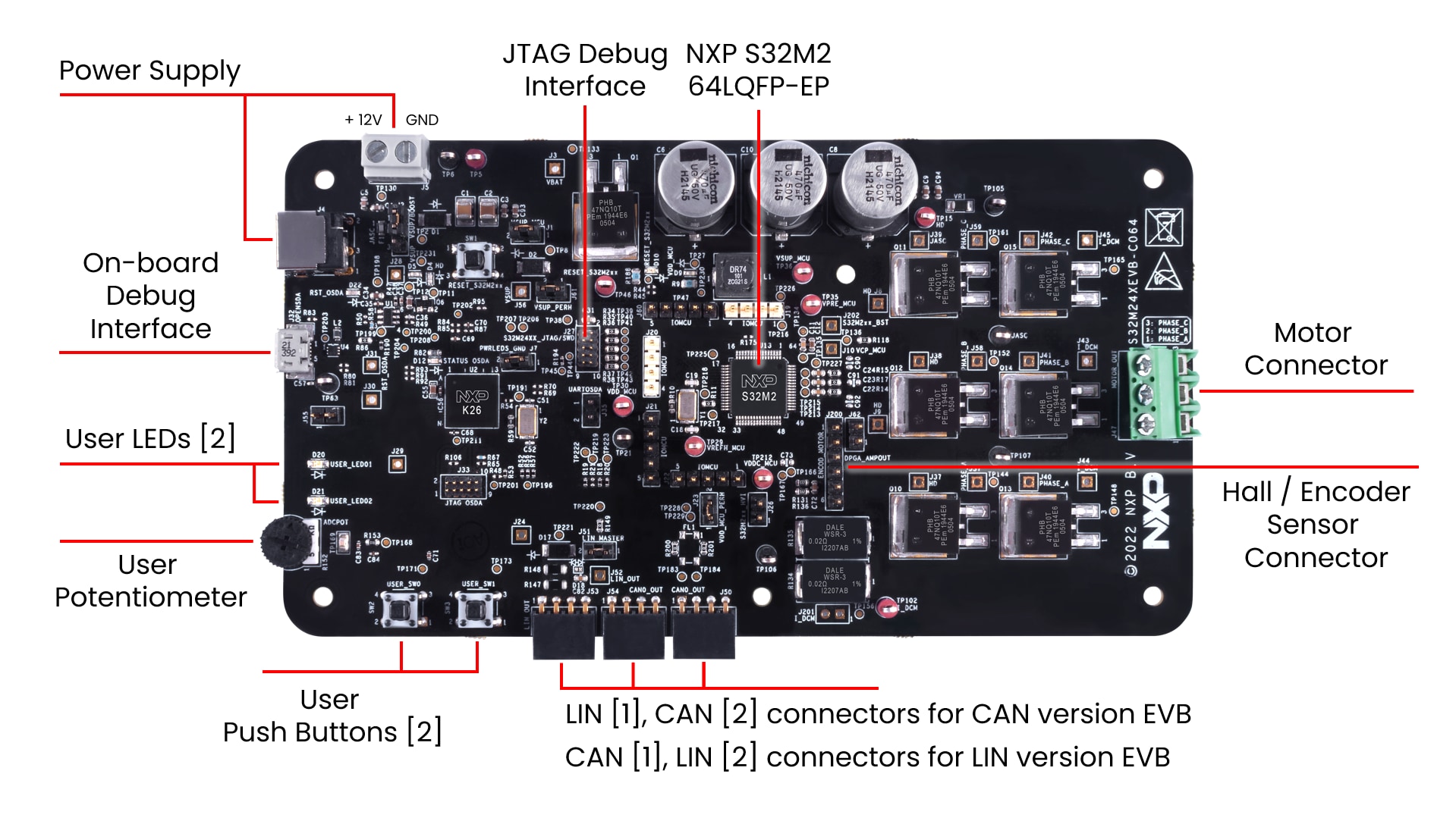
1. Out of the Box

2. Get Software
Sign in at NXP with your credentials

2.2 Install the S32M2xx Development Package
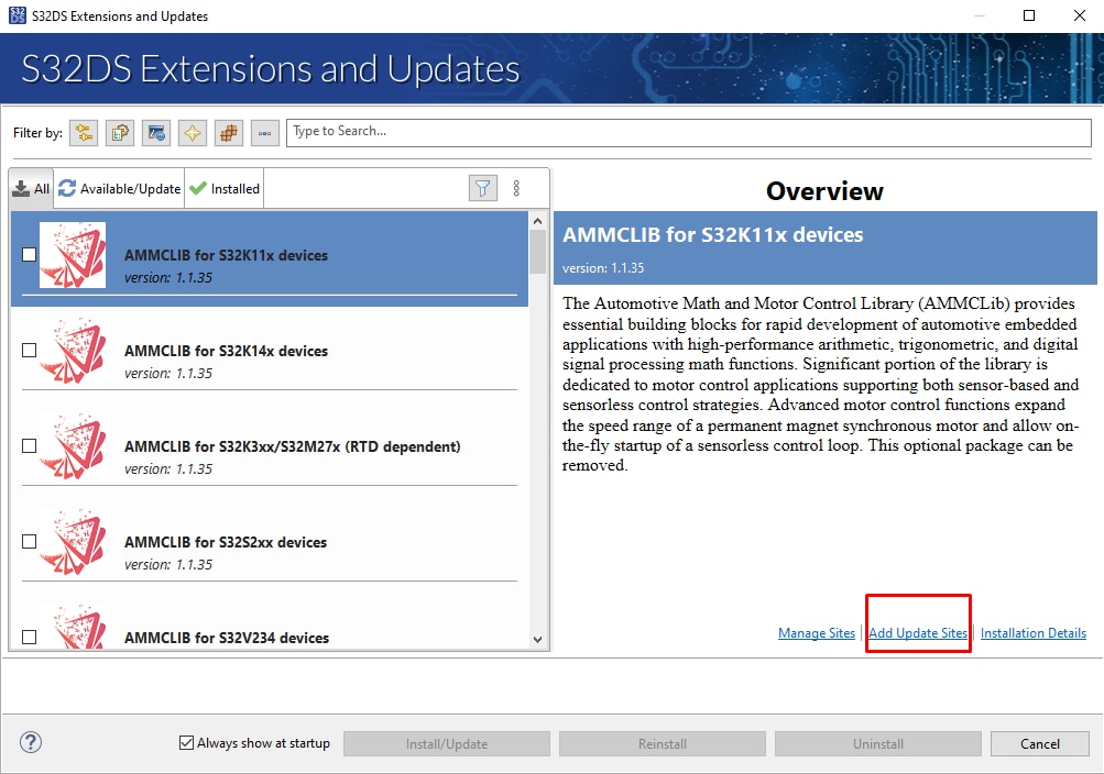
In S32DS, go to Help → S32DS Extensions and Updates from the top menu to open the S32DS Extensions and Updates dialogue.
Install S32M2xx Development Package

2.3 Download the RTD Drivers
Download RTD for S32K1 and S32M27x version 2.0.0.
Select "Automotive SW - S32K3/S32M27x - Real-Time Drivers for Cortex-M" package to download update site files.


2.4 Download the Patch for RTD Drivers
Download RTD for S32K3 and S32M27x version 4.0.0 patch P20.
Select Automotive SW - S32K3/S32M27x - real-time Drivers for Cortex-M package to download updatesite files.


2.5 Add the RTD Drivers to S32DS
In S32DS, go to Help → S32DS Extensions and Updates from the top menu to open the S32DS Extensions and Updates dialogue where you click on the "Add Update Sites" link.
Select downloaded: SW32K1_S32M27x_RTD_4.4_R21-11_2.0.0_D2308_DS_Updatesite.zip file (shorter one from the file names)
2.6 Install the RTD Drivers
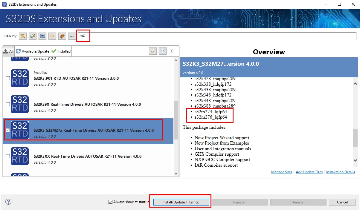
Install the RTD 2.0.0 from the list. Be aware that RTD 2.0.0 may appears in the list more than twice. Ensure that you selected the version that supports only/also S32M27x (See content of the Overview window on the right side)

2.7 Add the RTD Patch 04 to S32DS
Repeat the installation steps 2.5 and 2.6 also for patch P04 (the longer one from the file names): SW32K1_S32M24x_RTD_R21-11_2.0.0_P04_D2404_DS_updatesite.zip file.
Again, ensure that you selected the version that supports only/also S32M24x.
2.8 Get FreeMASTER Application Tool
Download and install FreeMASTER Application Tool for real-time debugging.

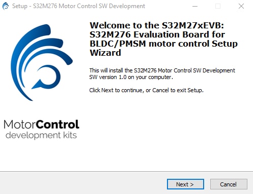
2.10 Get the Draft of S32M276 Motor Control Application
Download and install the S32M276 motor control application software.
3. Plug It In
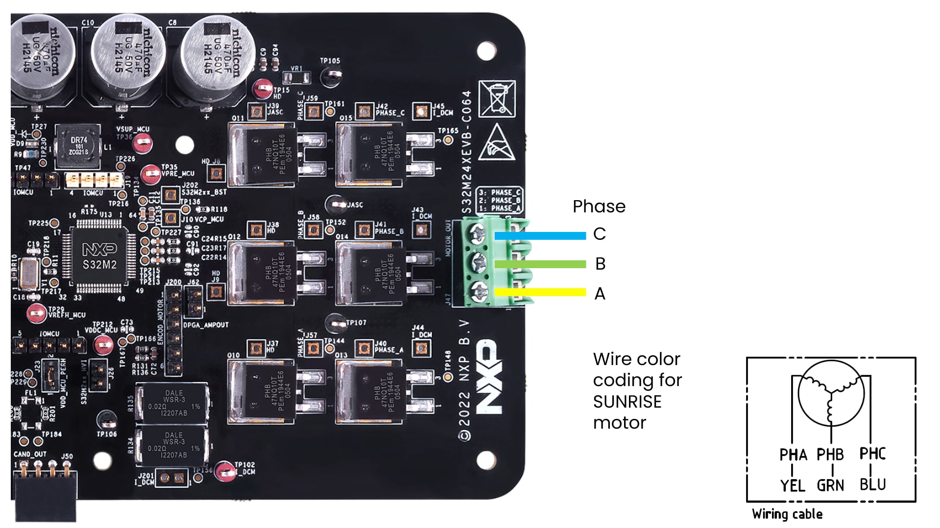
The recommended accessory kit for S32M27XEVB board is BLDC_KIT (software developed and tuned for given motor), however you may use any suitable 3 ph motor and 12 V power supply instead.
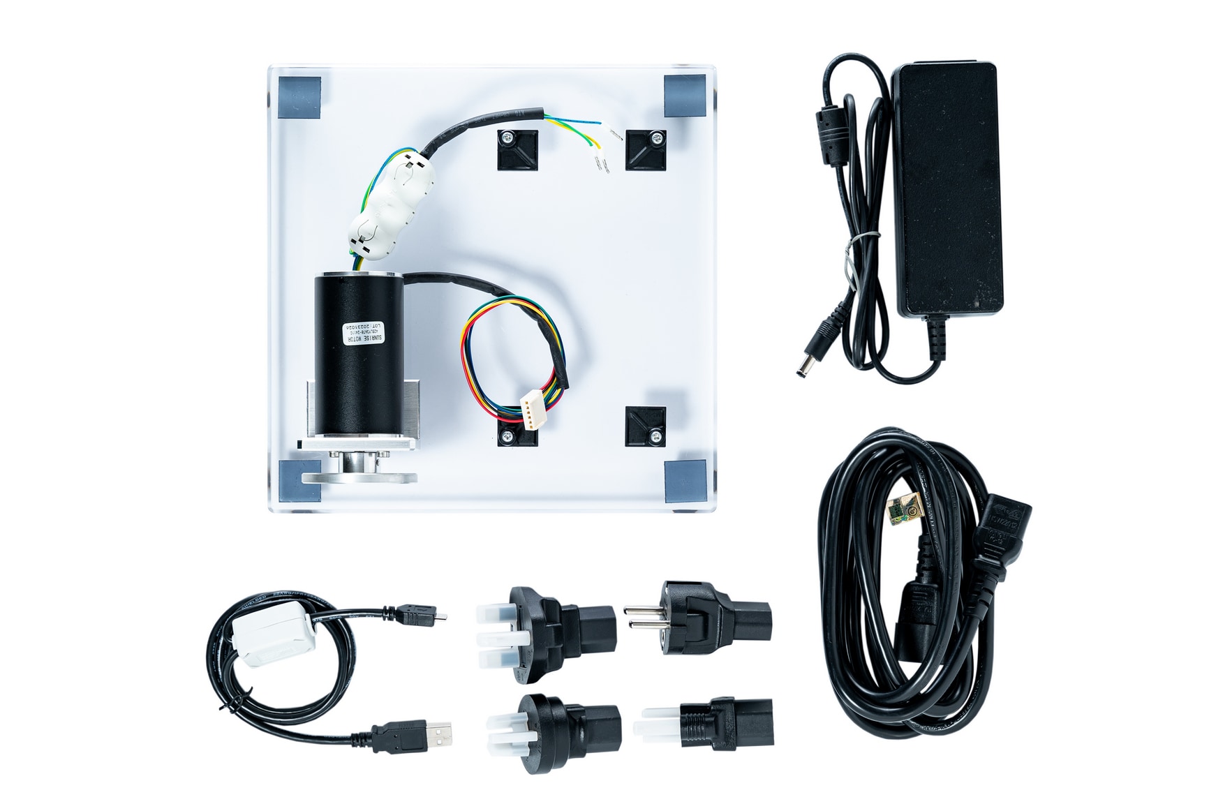
BLDC_KIT Content:
- 95 W BLDC motor with HALL sensors Sunrise 42BLY3A78-24110
- Plexiglass
- 12 V, 5 A power supply Meanwell GST60A12-P1J
- Power supply cable with set of universal plugs
- 4 self-adhesive standoffs for any EVB Takachi AST3-10B
- Micro-USB cable
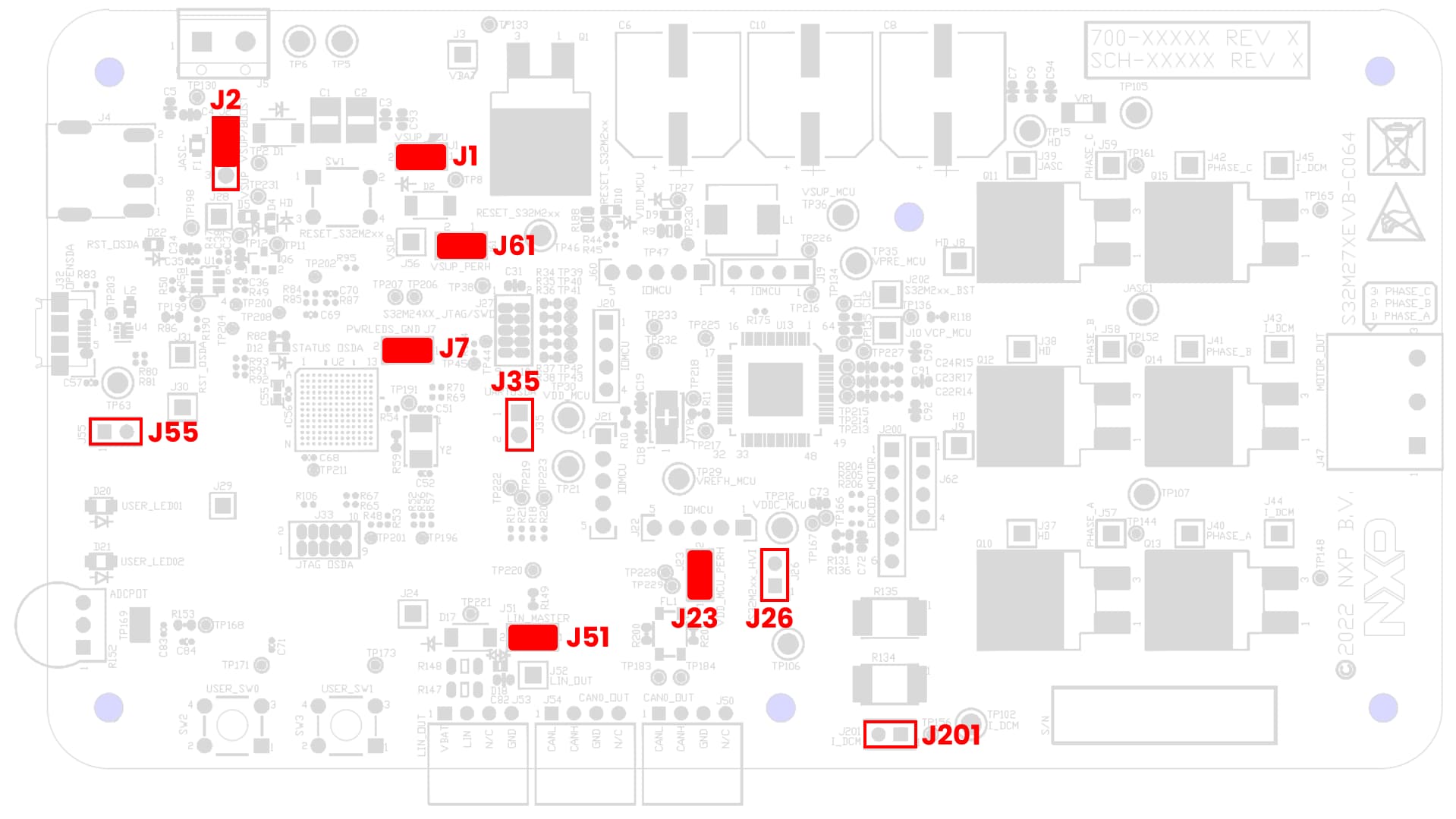
3.1 Check The Default Jumper Positions at the S32M27XEVB EVB
| S32M27XEVB Default Jumper Settings | ||
|---|---|---|
| Jumper | State | Notes |
J1 |
CLOSED | VSUP_MCU is routed to VSUP input of MCU |
J2 |
1-2 | VBAT is routed to VSUP. Boost Converter disconnected |
J7 |
CLOSED | Power domains LED Indicators enabled |
J23 |
CLOSED | VDD_MCU is connected to the VDD_MCU_PERH |
J26 |
OPEN | [1] High Voltage Input, [2] GND |
J35 |
OPEN | [1] LPUART0_RX, [2] LPUART0_TX |
J51 |
CLOSED | LIN Commander* mode |
J55 |
OPEN | ADC Potentiometer disabled |
J61 |
CLOSED | VSUP is routed to VSUP_PERH |
J201 |
OPEN | Current shunt voltage, not populated |
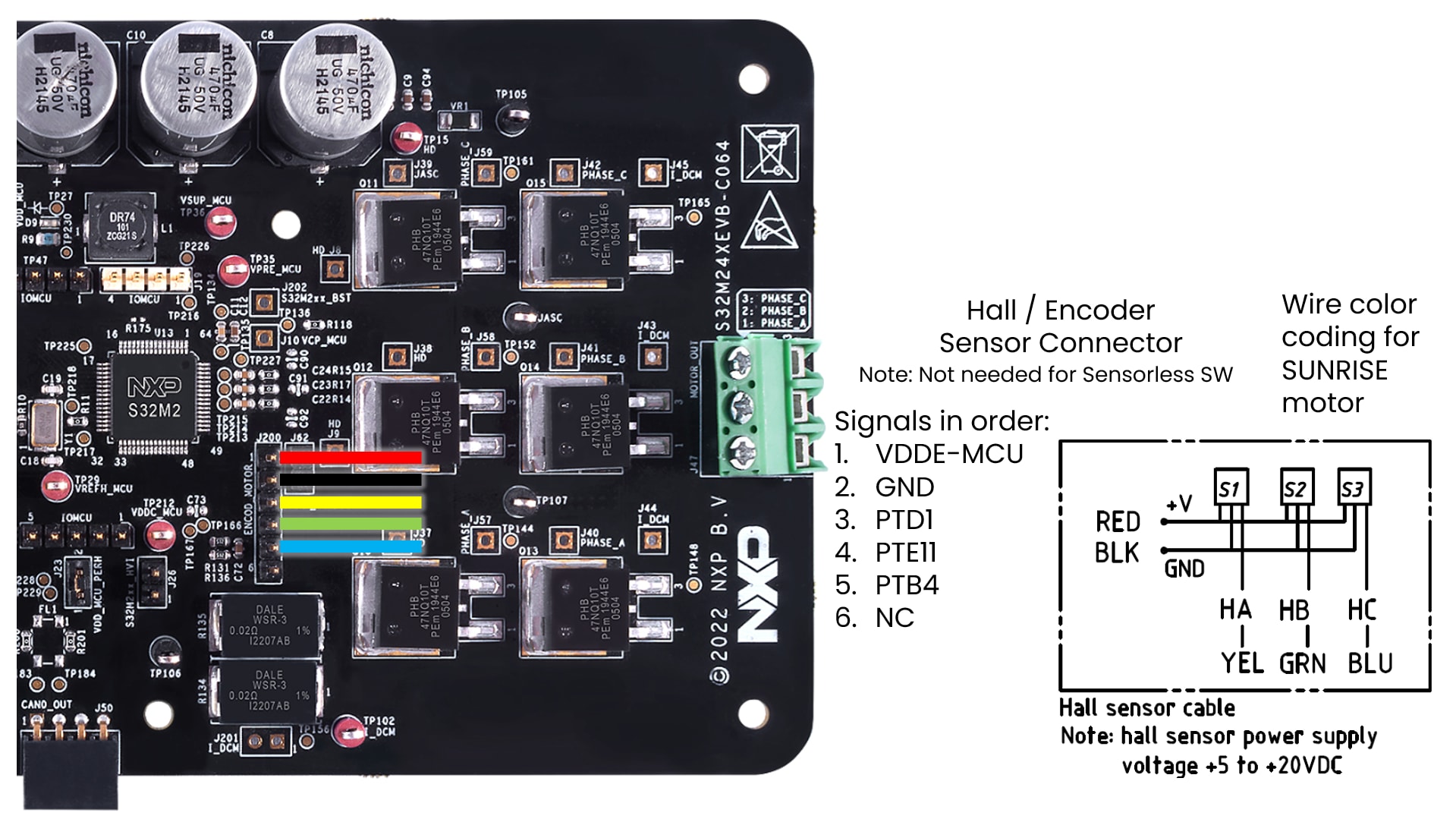
3.3 Plug In the Encoder/HALL Sensors
Optionally plug the Encoder/HALL sensors (only for sensor-based sw application)
4. Build
Let's take your S32M27XEVB motor control board for a test drive.
4.1 Select Application and MCU Programing
Select the appropriate PMSM or BLDC motor control application from the installed directory.
NXP\MC_DevKits\S32M27XEVB\sw
To import the installed application software project in the S32 Design Studio IDE for S32 Platform:
- Launch S32DS for S32 Platform
-
Go to File → Import, then select General → Existing Projects into Workspace

-
Navigate to the installed application directory:
NXP\MC_DevKits\ S32M276SFFR\swand choose appropriate project and click OK. Then, click Finish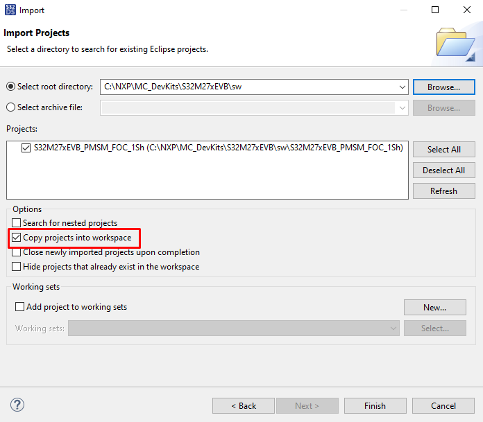
4.2 Use Configuration Tool
-
Unfold structure of the project with low-level drivers and double-click on *.mex file to open the project configuration in S32 Configuration Tool

-
Please ensure that you configure appropriate project and click on "Update Code" button for generating configuration files

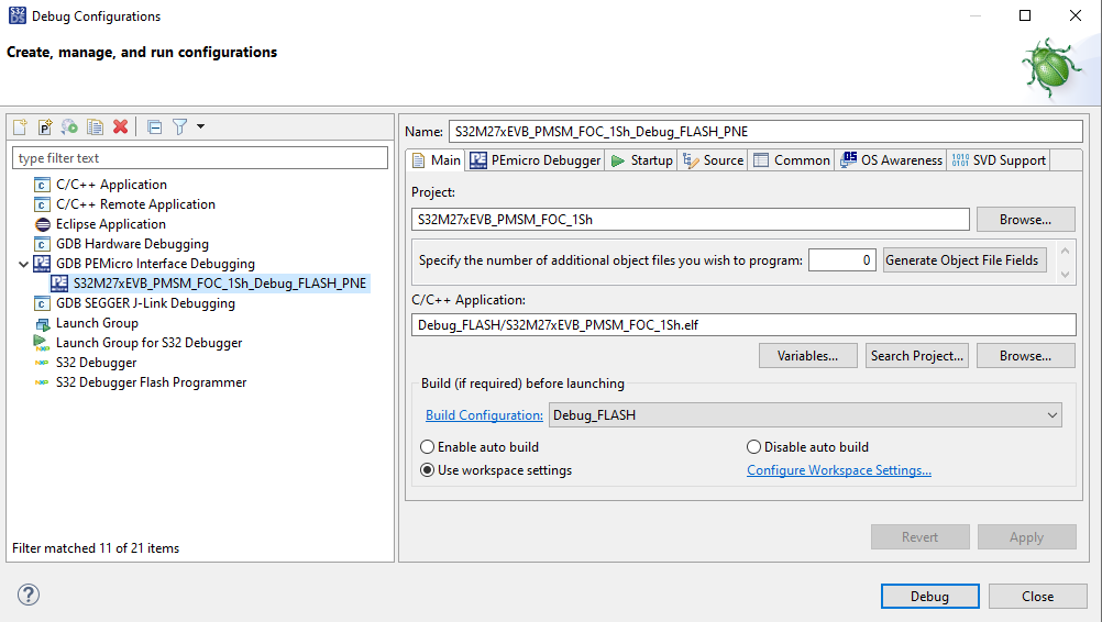
4.3 Upload Software and Debug
In S32DS, return back to the C/C++ perspective.
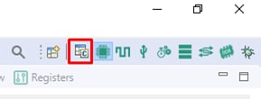
Use the Debug Configuration menu and select the predefined debug configuration for building and uploading software into MCU.

The S32DS will switch into debug perspective where you may let the code run by clicking on Resume (or press F8), and use Disconnect to avoid interference between the S32DS IDE debugger and the FreeMASTER tool.


4.4 Set Up the Debugging Tool
Launch the FreeMASTER application.
To open the *.pmpx FreeMASTER project <selected project>\FreeMASTER_control, click File → Open Project.
Launch the FreeMASTER application.

To enable communication, in the FreeMASTER tool bar, click Go (or press Ctrl + G).
Successful communication displays in the status bar at the bottom as: RS-232 UART Communication;COMn;speed = 115200

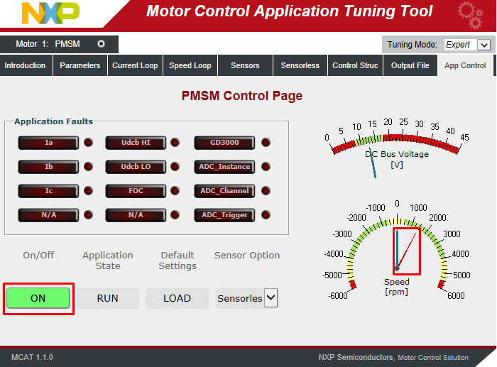
Application Control
Motor Parameters (Optional Step)
If you do not use BLDC_KIT (motor Sunrise 42BLY3A78-24110), you may need to edit the motor parameters according to used BLDC/PMSM motor. In the Motor Control Application Tuning (MCAT) Tool switch to Parameters tab and edit values on left side.
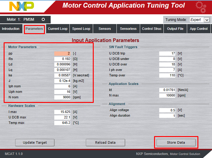
Once you finish, click on Store Data, switch to Output File tab and Generate static configuration file.

Now repeat step 4.3 to build the project and upload the code into MCU.
On this page
- 2.1
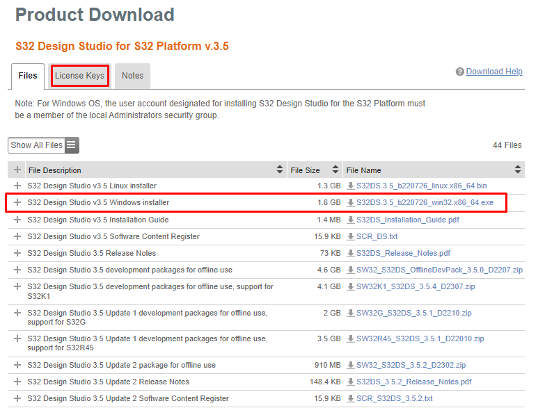
Download and Install IDE
- 2.2
Install the S32M2xx Development Package
- 2.3
Download the RTD Drivers
- 2.4
Download the Patch for RTD Drivers
- 2.5
Add the RTD Drivers to S32DS
- 2.6
Install the RTD Drivers
- 2.7
Add the RTD Patch 04 to S32DS
- 2.8
Get FreeMASTER Application Tool
- 2.9
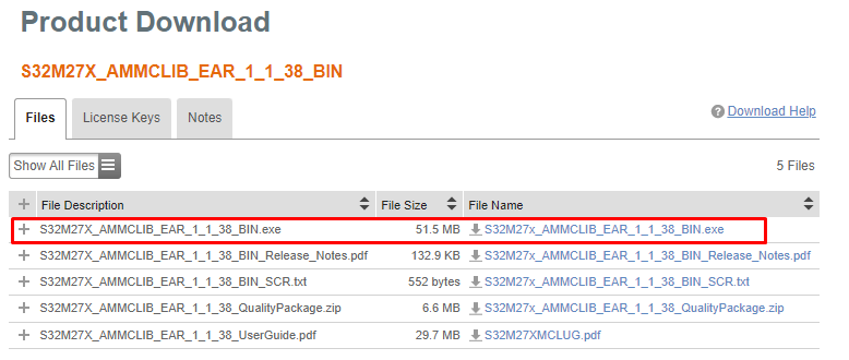
Get AMMCLib for S32M27X
- 2.10
Get the Draft of S32M276 Motor Control Application
- 3.1
Check The Default Jumper Positions at the S32M27XEVB EVB
- 3.2
Plug In the Motor
- 3.3
Plug In the Encoder/HALL Sensors
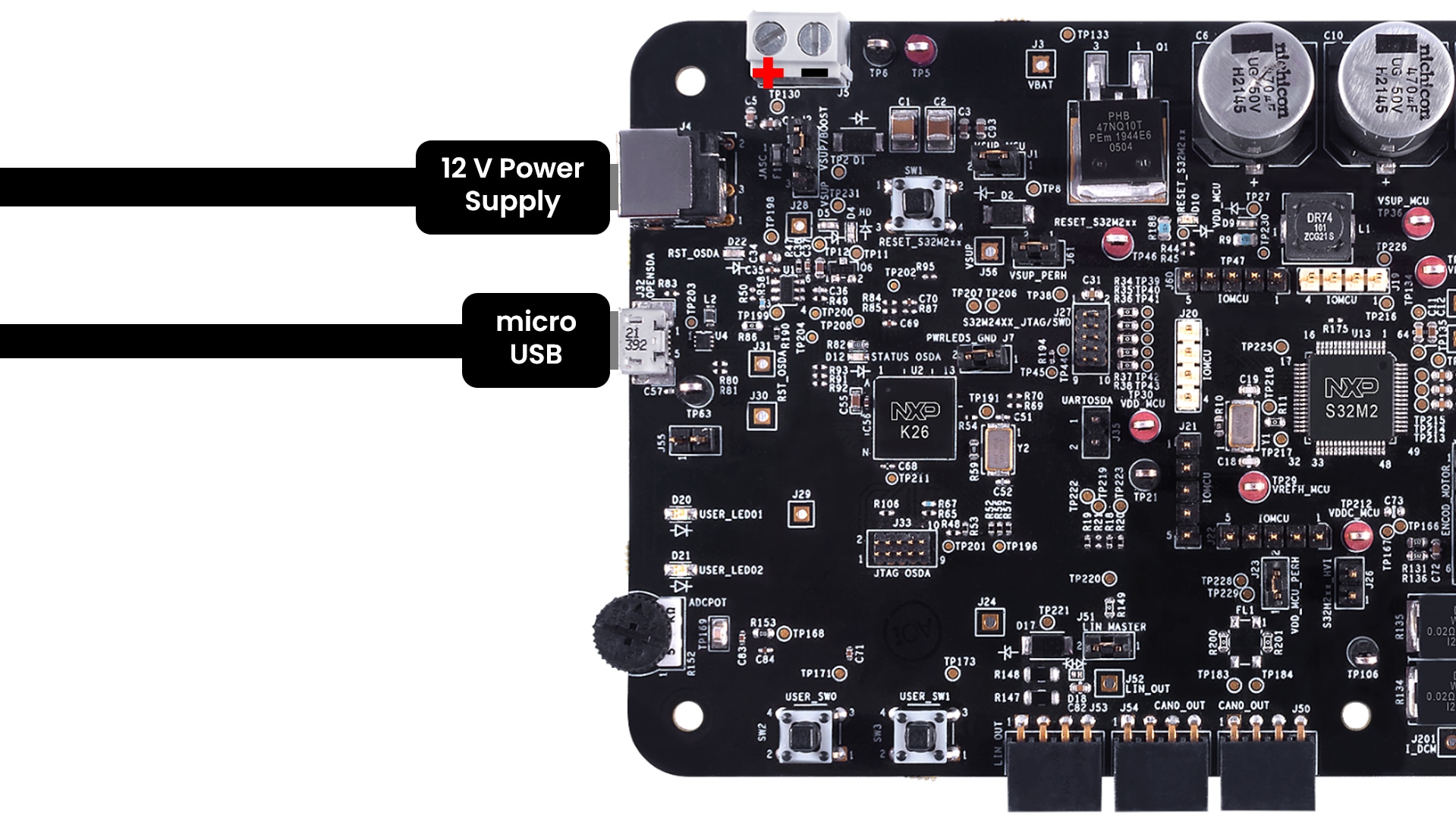
- 3.4
Plug In the Power Supply and USB Debug Interface
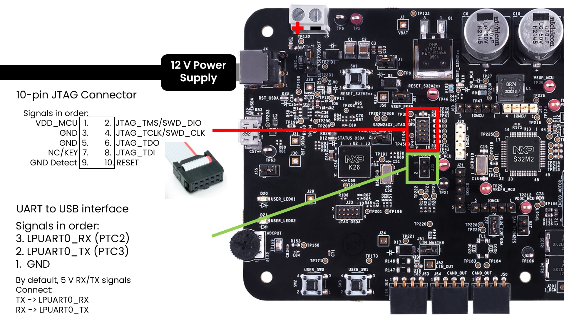
- 3.5
Plug In the JTAG Debug Interface and UART Interface