Getting Started with the S32K14W-Q064 Evaluation Board
Contents of this document
-
Out of the Box
-
Get Software
-
Plug It In
-
Build, Run
Sign in to save your progress. Don't have an account? Create one.

Purchase your S32K14W-Q064 Evaluation Board for Automotive General Purpose
1. Out of the Box
You can watch the video or follow the below step-by-step guide to set up your S32K14WEVB-Q064 Evaluation Board:


2. Get Software
2.1 Get the Integrated Development Environment (IDE)
S32K14WEVB-Q064 performs better when using S32 Design Studio for the S32 Platform.
DOWNLOAD S32 DESIGN STUDIO IDE2.2 Install S32K1 Drivers
Run the S32 Design Studio, Go to menu → Help → S32DS Extension and Updates.
Install S32K1xx development package and continue in installation either with SDK or with RTD drivers.


2.3 Get the Run-Time Debugging Tool
S32K14EVB-Q064 evaluation board performs better when using the FreeMASTER tool for run-time debugging.
You can also download and install the FreeMASTER Communication Driver (source code already included in the example project).
DOWNLOAD FREEMASTER TOOL - Link3. Plug It In
3.1 Set Up Jumpers in the S32K14WEVB-Q064 Evaluation Board
| Jumper | Configuration | Description |
|---|---|---|
J10 |
2-3 | MCU Voltage [5V] |
J15 |
CLOSED | MCU Current Measurement Pins |
J104 |
1-2 | RESET Push Button [Bypass to MCU] |
J107 |
2-3 | Power Source [USB] |
J108 |
CLOSED | LIN Mode [Master] |


4. Build, Run
4.1 Create an S32DS Project from Example
Open S32DS and from the menu, go to File → New → S32DS Project from Example

Select for example ADC project either from SDK or from RTD


4.2 Configure and Build Project
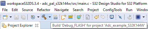
The SDK project might be built directly via “Build button”

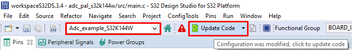
While RTD project needs to generate the configuration. Double-click on mex file to open Configuration Tool and click on the Update Code button for configuration files generation.


Once you finish your code/configuration modification, click on built button.


Introduction to OpenSDA
OpenSDA is an open-standard serial and debug adapter. It bridges serial and debug communications between a USB host and an embedded target processor. OpenSDA software includes a flash-resident USB mass-storage device (MSD) bootloader and a collection of OpenSDA applications.
The S32K14WEVB-Q064 comes with the MSD Flash Programmer OpenSDA Application preinstalled.
Follow these instructions to run the OpenSDA Bootloader and update or change the installed OpenSDA Application.
| Enter OpenSDA Bootloader Mode | Load an OpenSDA Application |
|---|---|
A removable drive should now be visible in the host file system with a volume label of BOOTLOADER. You are now in OpenSDA Bootloader mode. |
You are now running the latest version of the MSD Flash Programmer. Use this same procedure to load other OpenSDA Applications. |
The MSD Flash Programmer is a composite USB application that provides a virtual serial port and an easy and convenient way to program applications into the S32K1 MCU. It emulates a FAT16 file system, appearing as a removable drive in the host file system with a volume label of S32K14WEVB-Q064. Raw binary and Motorola S-record files that are copied to the drive are programmed directly into the flash of the S32K1 and executed automatically. The virtual serial port enumerates as a standard serial port device that can be opened with standard serial terminal applications.
| Using the MSD Flash Programmer | Using the Virtual Serial Port |
|---|---|
The new application should now be running on the S32K14WEVB-Q064. Starting with v1.03 of the MSD Flash Programmer, you can program repeatedly without the need to unplug and reattach the USB cable before reprogramming.
Drag one of the |
|
On this page
- 2.1
Get the Integrated Development Environment (IDE)
- 2.2
Install S32K1 Drivers
- 2.3
Get the Run-Time Debugging Tool
- 3.1
Set Up Jumpers in the S32K14WEVB-Q064 Evaluation Board
- 3.2
Connect the Debugger Cable
- 3.3
Test Your Board With the Out the Box Demo Software
- 4.1
Create an S32DS Project from Example
- 4.2
Configure and Build Project
- 4.3
Load Code into MCU
- 4.4
Debug the Code