Getting Started with the RDGD3162CSL3PEVM Reference Design
Contents of this document
-
Out of the Box
-
Get Hardware
-
Configure Software
-
Configure Hardware
Sign in to save your progress. Don't have an account? Create one.
Purchase your RDGD3162CSL3PEVM
1. Out of the Box
The NXP analog product development boards provide an easy-to-use platform for evaluating NXP products. The boards support a range of analog, mixed-signal and power solutions. They incorporate monolithic integrated circuits and system-in-package devices that use proven high-volume technology. NXP products offer longer battery life, a smaller form factor, reduced component counts, lower cost, and improved performance in powering state-of-the-art systems.
This page will guide you through the process of setting up and using the RDGD3162CSL3PEVM board.
1.1 Kit Contents and Packing List
The RDGD3162CSL3PEVM kit contents include:
- Assembled and tested RDGD3162CSL3PEVM (three-phase inverter populated with 5.0 V compatible gate driver devices) board in an antistatic bag
- KITGD316xTREVB 3.3 V to 5.0 V translator with FRDM-KL25Z MCU board with micro‑USB cable
- Quick start guide
1.2 Additional Hardware
In addition to the kit contents, the following hardware is beneficial when working with this kit:
- Microcontroller for SPI communication
- Compatible Bosch compact silicon carbide line (CSL) B-sample SiC MOSFET module
- DC link capacitor compatible with SiC MOSFET module
- HV power supply with protection shield and hearing protection
- Current sensors for monitoring each phase current
- 12 V, 1.0 A DC power supply
- 4-channel oscilloscope with appropriate isolated probes
1.3 Windows PC Workstation
This reference design requires a Windows PC workstation. Meeting these minimum specifications produces great results when working with this evaluation board.
- USB-enabled computer with Windows 8 or Windows 10
1.4 Software
Installing software is necessary to work with this reference design. All listed software is available on the information page at: RDGD3162CSL3PEVM.
- FlexGUI software for using with KITGD316xTREVB MCU/translator board
- S32S Design Studio IDE for power architecture
- Automotive Math and Motor Control Library (AMMCLib)
- FreeMASTER 2.0 runtime debugging tool
- Motor control application tuning (MCAT)
- Example code, GD3162 device driver notes, and GD31xx device driver reference
2. Get Hardware
2.1 Board Features
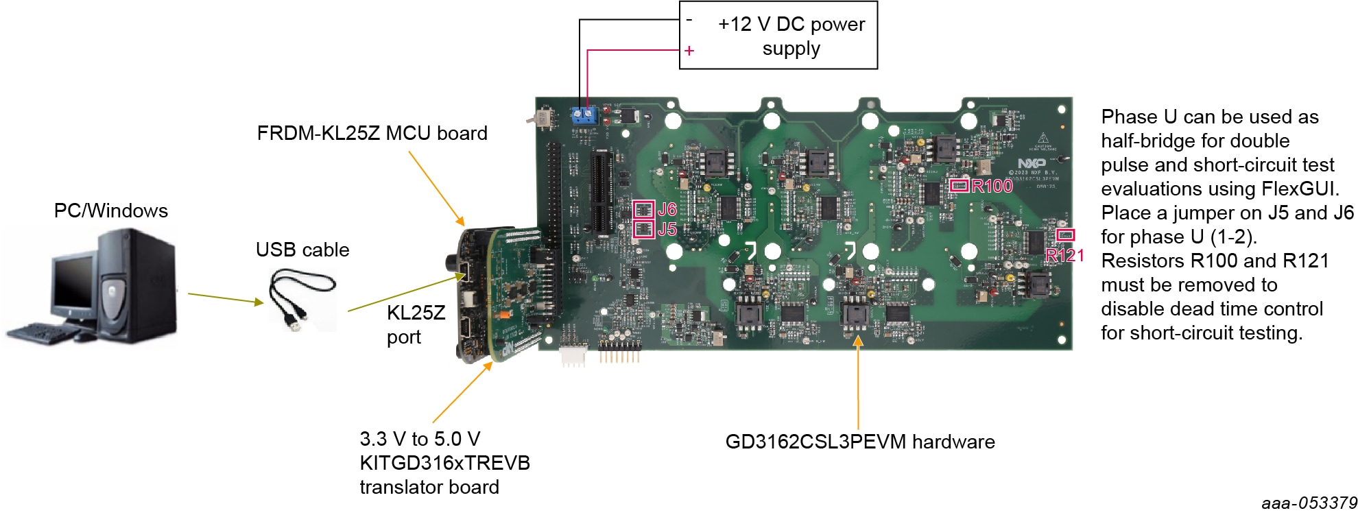
- Capability to perform double pulse and short-circuit tests on phase U using KITGD316xTREVB and FlexGUI; see phase U schematics and FlexGUI pulse tab
- Evaluation board designed for and populated with GD3162 gate drivers and protection circuitry
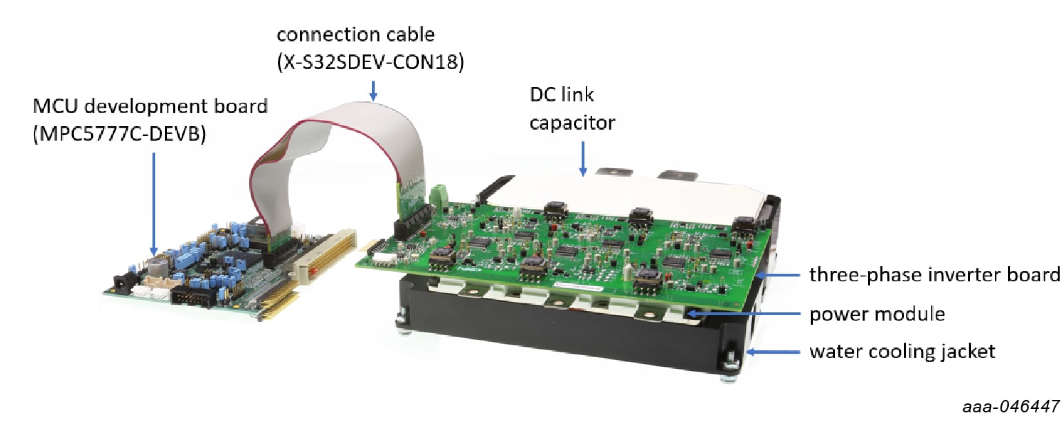
- Capability to connect to Bosch CSL B-sample SiC specific modules for full three-phase evaluation and development
- Daisy chain SPI communication × 3 - 2 channel (three high-side gate drivers and three low-side gate drivers) or x 6 - 1 channel (all six gate drivers)
- Variable flyback VCC power supply with GND reference and variable negative VEE supply
- Easy access to power, ground, and signal test points
- 2 x 32 peripheral component interconnect express (PCIe) socket for interfacing MCU control MPC5775B/E‑EVB, MPC5777C-DEVB, or MPC57744P
- Optional connection for DC bus voltage and current monitoring
- Phase current feedback connections
- Resolver signal connector
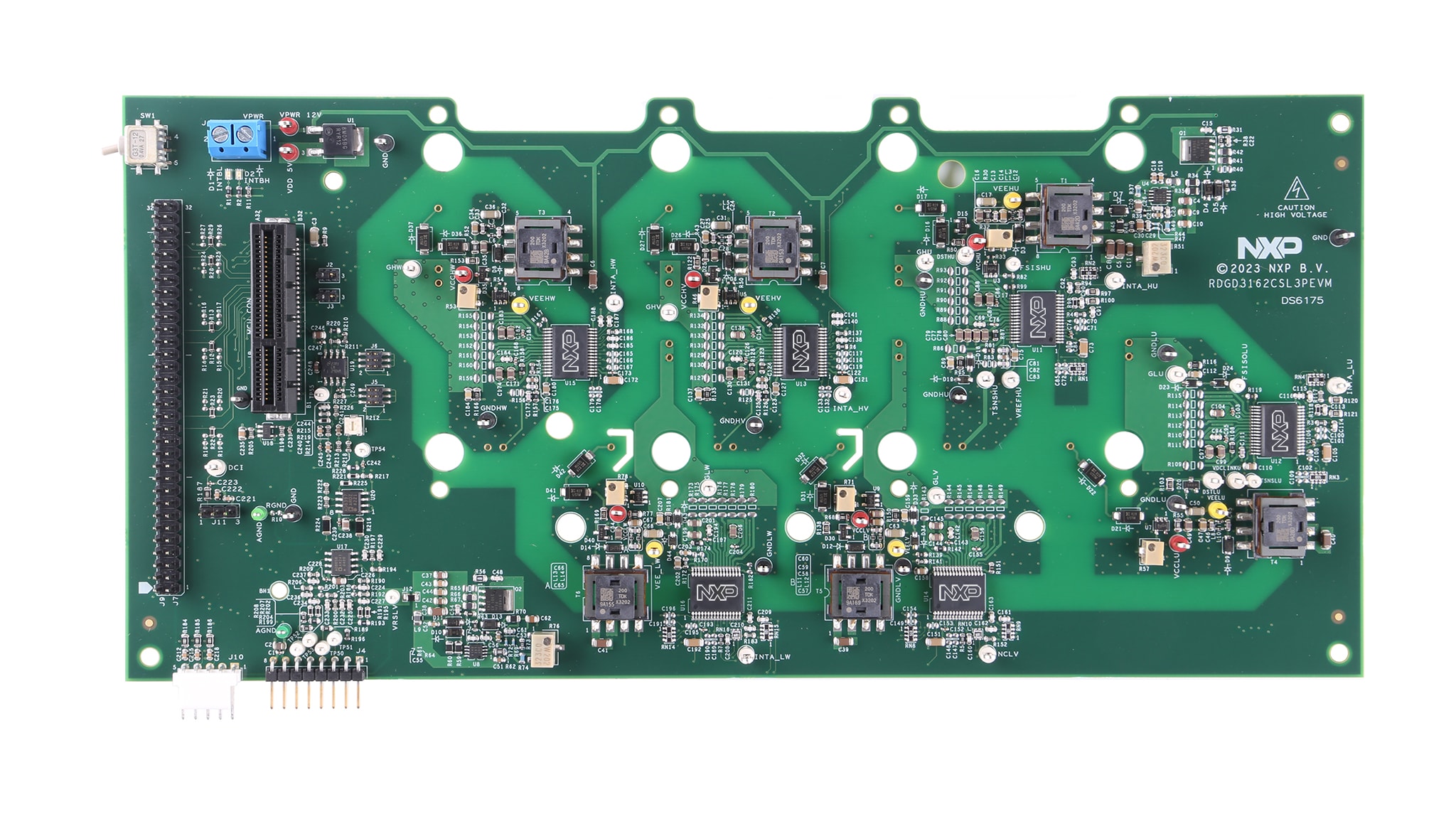
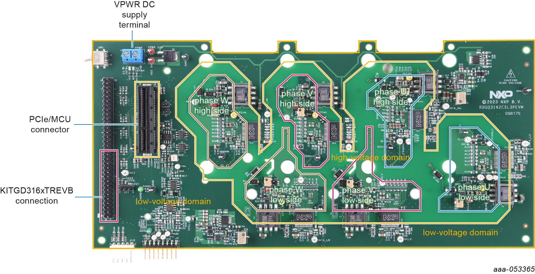
2.2 Board Description
The RDGD3162CSL3PEVM is a fully functional three-phase inverter evaluation board populated with six GD3162 gate drivers with fault management and supporting circuitry.
This board supports serial peripheral interface (SPI) daisy chain communication for programming and communication with three high-side gate drivers and three low-side gate drivers independently, or all six gate drivers at the same time.
3. Configure Software
3.1 Install and Configure Software and Tools
Software for RDGD3162CSL3PEVM is distributed with the FlexGUI tool. Necessary firmware comes preinstalled on the FRDM-KL25Z with the kit.
Even if you intend to test with other software or PWM, it is recommended to install this software as a backup or to help debugging.
4. Configure Hardware
4.1 Configure Hardware
RDGD3162CSL3PEVM with KITGD316xTREVB attached as shown in Figure 1 using Windows-based PC and FlexGUI software.
Suggested equipment needed for test:
- Rogowski coil high-current probe
- High-voltage differential voltage probes
- High sample rate digital oscilloscope with probes
- DC link capacitor compatible with Bosch CSL B-sample power module
- Bosch CSL B-sample SiC power module
- Windows-based PC
- High-voltage DC power supply for DC link vol
- Low-voltage DC power supply for VPWR – +12 V DC gate drive board low-voltage domain
- Voltmeter for monitoring high-voltage DC link supply
- Load coil for double pulse testing (phase U only)
Design Resources
Additional References
In addition to our 3-Phase Inverter Reference Design Using the GD3162 with BOSCH CSL B SiC page, you may also want to visit: