Getting Started with the RDBESS772BJBEVB Battery Junction Box
Contents of this document
-
Out of the Box
-
Get Hardware
-
Configure Hardware
Sign in to save your progress. Don't have an account? Create one.
Purchase your RDBESS772BJBEVB
1. Out of the Box
The NXP analog product development boards provide an easy-to-use platform for evaluating NXP products. The boards support a range of analog, mixed-signal and power solutions. They incorporate monolithic integrated circuits and system-in-package devices that use proven high-volume technology. NXP products offer longer battery life, a smaller form factor, reduced component counts, lower cost and improved performance in powering state-of-the-art systems.
This page will guide you through the process of setting up and using the RDBESS772BJBEVB battery junction box.
2. Get Hardware
2.1 Board Features
The RDBESS772BJBEVB offers the following features.
- Four positive high-voltage measurement inputs (up to 1800 V)
- Two bipolar high-voltage measurement inputs (from −1800 V to 1800 V)
- Isolation monitoring between high-voltage and low-voltage domains
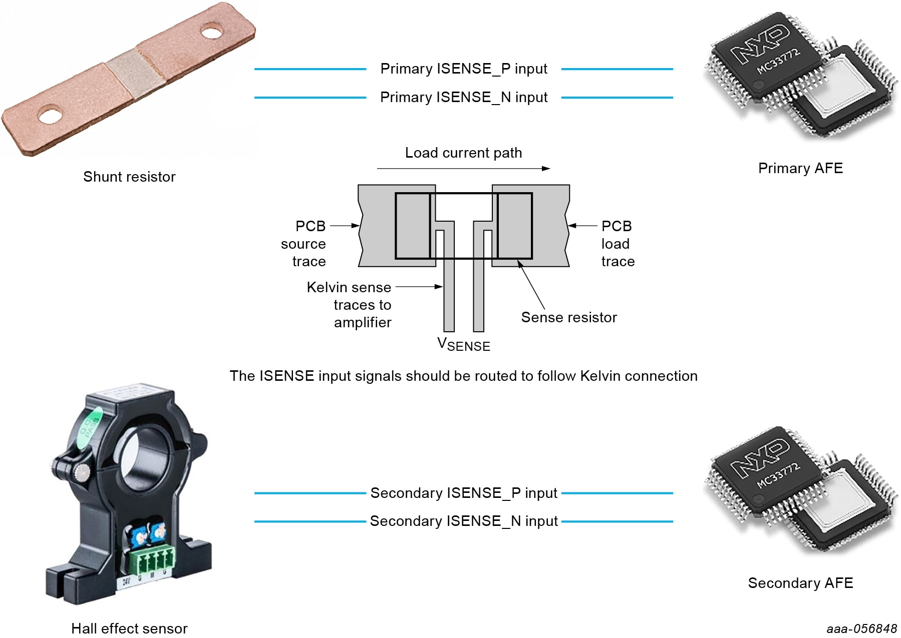
- Current measurement with a 100 µΩ shunt resistor (from −500 A to 500 A) with the option for redundancy using two shunt resistors
- Shunt resistor temperature estimation
- The option to have onboard shunt resistors or external shunt resistors
- One hall sensor for current measurement (from 0 A to 500 A) with the option to have another Hall sensor
- Precharge resistor temperature measurement with an external sensor
- Two EEPROMs for calibration data storage
- Galvanically isolated ETPL for communication
- Printed-circuit board designed according to IEC 60664 (pollution degree 3, material group IIIb)
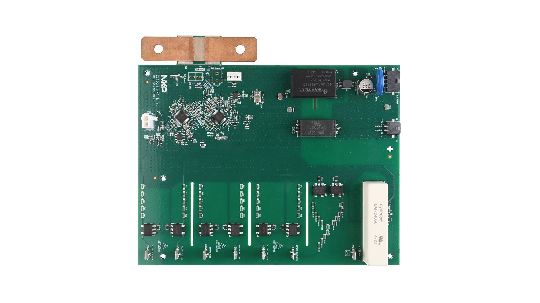
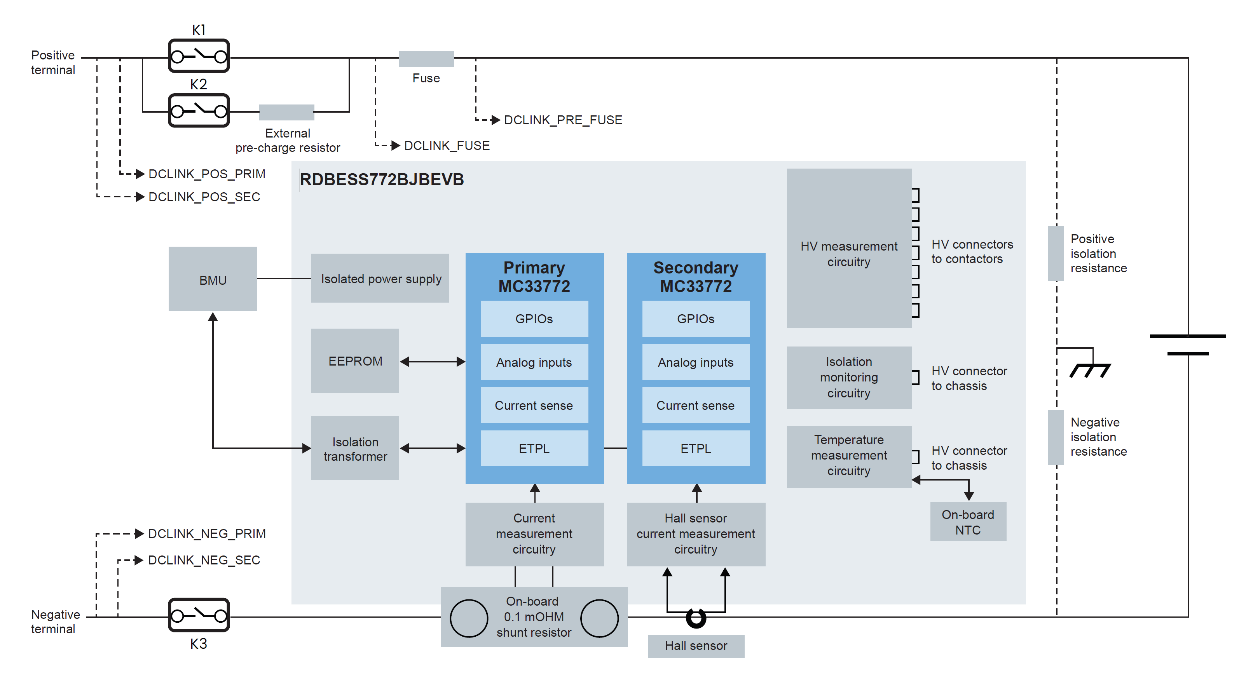
2.2 Board Description
The RDBESS772BJBEVB supports battery current measurement, contactor and fuse monitoring, isolation monitoring and temperature measurement.
The battery management unit (BMU) communicates and controls the two MC33772CTC1AEs. These ICs provide the necessary features to fulfill the various measurements.
3. Configure Hardware
3.1 Power Supply
The RDBESS772BJBEVB usually receives power from the BMU on the connector J12.
The power supply must follow the characteristics described in Table 1.
| Symbol | Parameter | Conditions | Min | Typ | Max | Unit |
|---|---|---|---|---|---|---|
| VBJB_PWR_IN | Supply voltage | - | 18 | 24 | 30 | V |
| IBJB_PWR_IN | Supply current | RDBESS772BJBEVB in Normal mode; TPL communication active; all high voltage switches enabled | - | 160 | 200 | mA |
| RDBESS772BJBEVB not active | - | 20 | - | mA |
The BMU is in the low-voltage domain, whereas the BJB is in the high-voltage domain. Therefore, the RDBESS772BJBEVB embeds an isolated DC-DC converter to power the MC33772C and the measurement circuitry. This converter is by default an industrial component.
Design Resources
Additional Resources
In addition to our 1500 V Battery Energy Storage Reference Design page, you may also want to visit: