Getting Started with the RD33774PC3EVB Evaluation Board
Contents of this document
-
Out of the Box
-
Get Hardware
-
Configure Hardware
Sign in to save your progress. Don't have an account? Create one.
Purchase your HVBMS | Centralized Cell Monitoring Unit (CMU)
1. Out of the Box
The NXP analog product development boards provide an easy-to-use platform for evaluating NXP products. The boards support a range of analog, mixed-signal and power solutions. They incorporate monolithic integrated circuits and system-in-package devices that use proven high-volume technology. NXP products offer longer battery life, a smaller form factor, reduced component counts, lower cost, and improved performance in powering state-of-the-art systems.
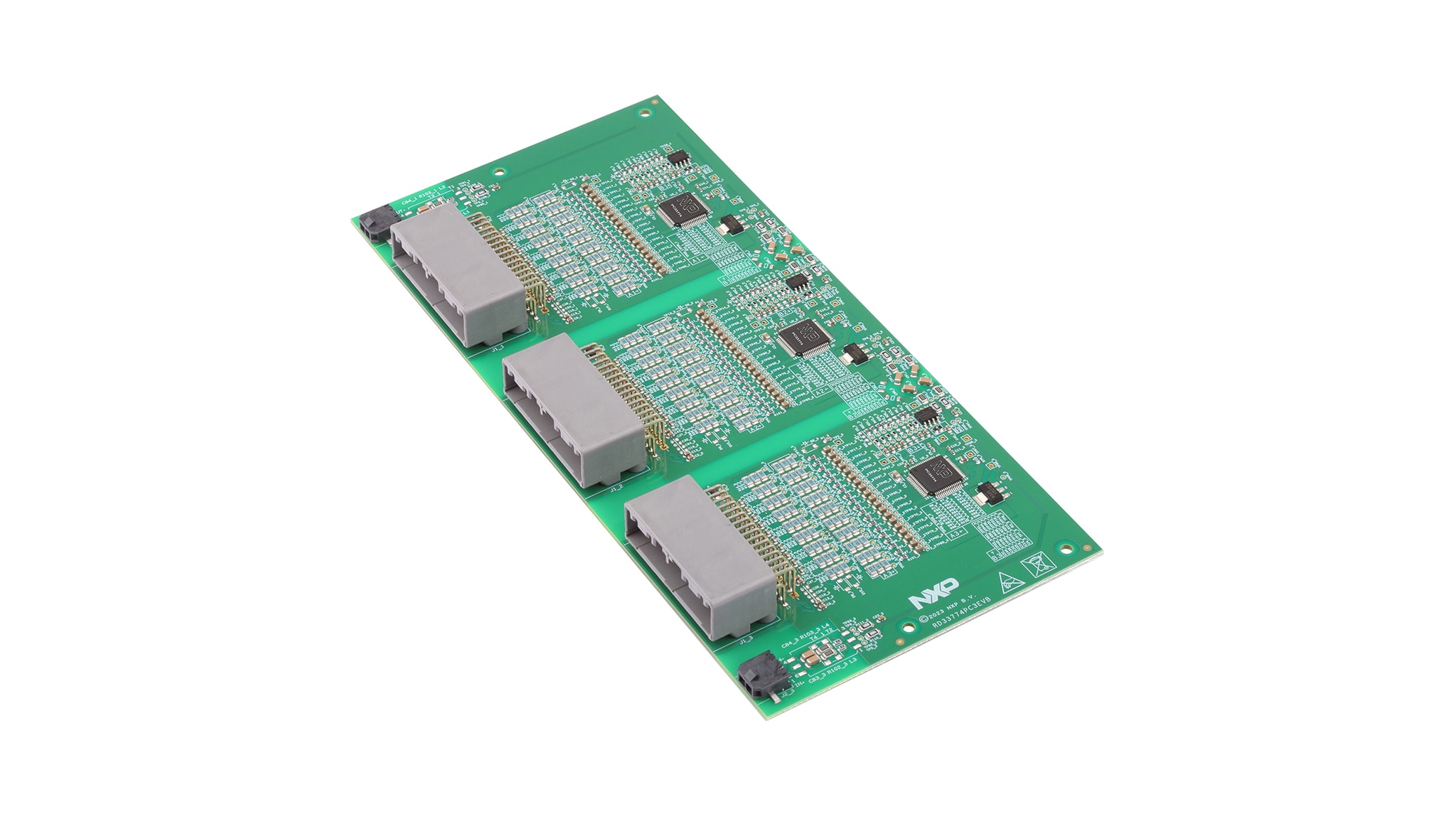
This page will guide the user through the process of setting up and using the RD33774PC3EVB board.
1.1 Kit Contents and Packing List
- Assembled and tested evaluation board/module in antistatic bag
- Three cell terminal cables
- Transformer physical layer (TPL) cable
1.2 Additional Hardware
In addition to the kit contents, the following hardware is necessary or beneficial when working with this kit:
- A 4-cell to 18-cell battery pack or a battery pack emulator, such as BATT-18EMULATOR
- FRDMDUALK3664EVB (EVB for MC33664A) with the S32K3X4EVB-T172 (S32K3X4 EVB) to interface with a PC
- For the evaluation setup, a graphical user interface, EvalGUI 7, is available in Secure Files at this link: MC33775A Evaluation GUI V7
1.3 Minimum System Requirements
This evaluation board requires a Windows PC workstation.
- USB-enabled computer with Windows 7 or Windows 10
- FTDI USB serial port driver (for FT230X Basic UART device)
1.4 Software
Installing software is necessary to work with this evaluation board. All listed software is available (under NDA) on the evaluation board page RD33774PC3EVB.
2. Get Hardware
2.1 Board Features
- Reference design with three MC33774ATP, showing optimized BOM as outlined in data sheet
- Capacitive isolation for onboard communication
- Based on NXP core layout for MC33774ATP; core layout is used for NXP internal electromagnetic compatibility (EMC) and hotplug tests
- Four-layer board, all components are assembled only on the top side
- Cell electrostatic discharge (ESD) capacitors package 0805
- 0805 packages used for all signals with a voltage higher than approximately 25 V
- Three 1206 surface-mounted device (SMD) resistors per balancing channel for individual cell-voltage balancing
- All eight external thermistor inputs are available
- Placeholder for I²C-bus EEPROM
- Can be used together with the 800 V HVBMS reference design or the evaluation setup
2.2 Board Description
The main features of the RD33774PC3EVB are:
- Reference design with three MC33774ATP, showing optimized BOM as outlined in data sheet
- Capacitive isolation for onboard communication
- Based on NXP core layout for MC33774ATP; core layout is used for NXP internal electromagnetic compatibility (EMC) and hotplug tests
- Four-layer board, all components are assembled only on the top side
- Cell electrostatic discharge (ESD) capacitors package 0805
- 0805 packages used for all signals with a voltage higher than approximately 25 V
- Three 1206 surface-mounted device (SMD) resistors per balancing channel for individual cell-voltage balancing
- All eight external thermistor inputs are available
- Placeholder for I²C-bus EEPROM
- Can be used together with the 800 V HVBMS reference design or the evaluation setup
3. Configure Hardware
This section gives guidance on how to set up and run the RD33774PC3EVB evaluation board and GUI.
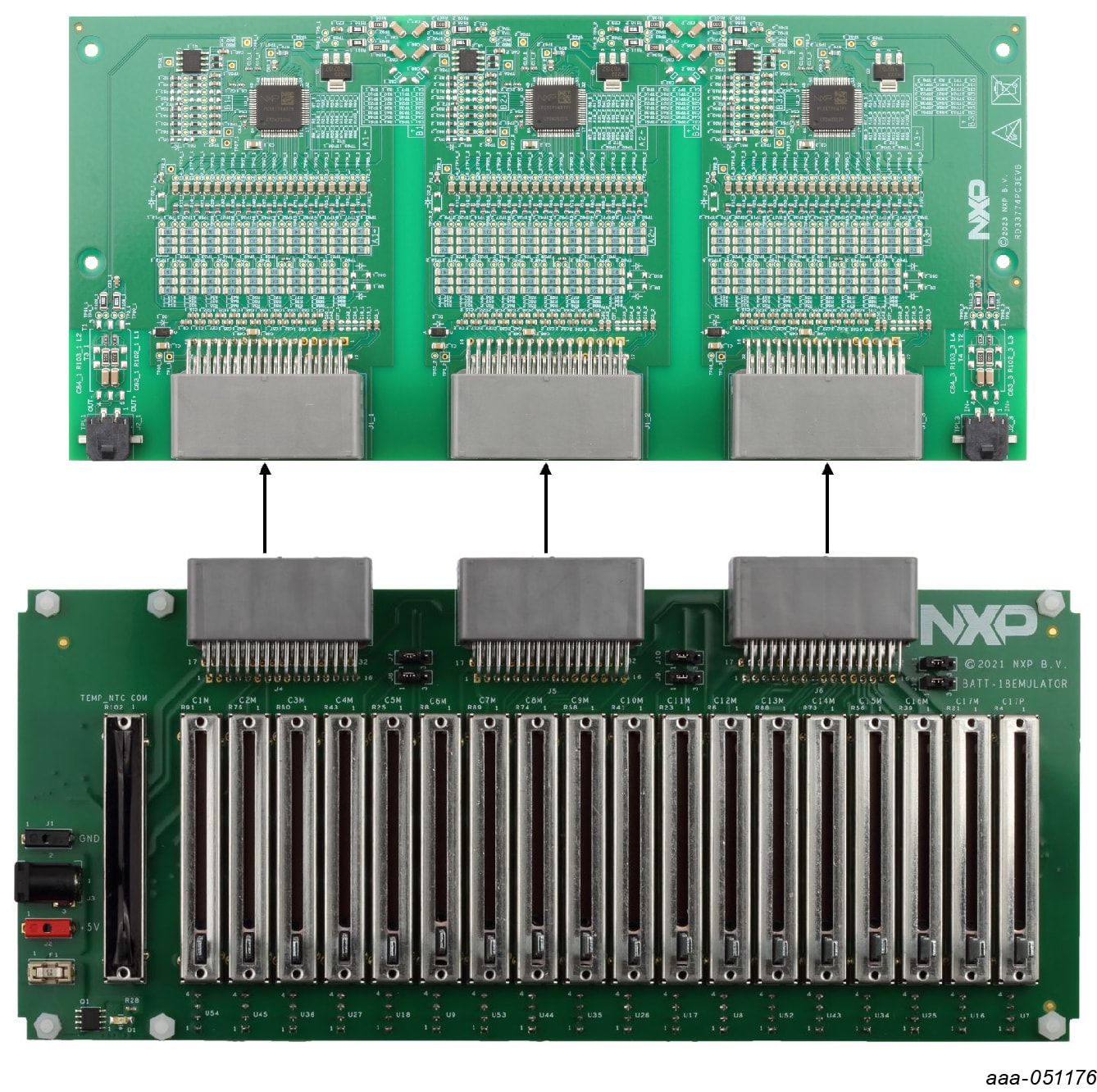
3.1 Battery Emulator Connection
A minimum of four cells and a maximum of 18 cells can be monitored by one MC33774ATP. NXP provides an 18-cell battery emulator board, BATT-18EMULATOR. This board provides an intuitive way to change the voltage across any of the 18 cells of an emulated battery pack. The board RD33774PC3EVB can be connected to an 18-cell battery emulator board using the connectors J1_1, J1_2 and J1_3, with the provided supply cable. See Figure 2.
Design Resources
Additional References
In addition to the MC33774, 18 Channel Li-Ion Battery Cell Controller IC ASIL D page, visit: