Getting Started with the RD33774ADSTEVB Evaluation Board
Contents of this document
-
Out of the Box
-
Get Hardware
-
Configure Hardware
Sign in to save your progress. Don't have an account? Create one.
Purchase your RD33774ADSTEVB
1. Out of the Box
The NXP analog product development boards provide an easy-to-use platform for evaluating NXP products. The boards support a range of analog, mixed-signal and power solutions. They incorporate monolithic integrated circuits and system-in-package devices that use proven high-volume technology. NXP products offer longer battery life, a smaller form factor, reduced component counts, lower cost and improved performance in powering state-of-the-art systems.
This page will guide you through the process of setting up and using the RD33774ADSTEVB board.
2. Get Hardware
2.1 Board Features
- Daisy-chain device connection
- LED indicator for operation mode
- Cell-balancing resistors (22 Ω per individual cell)
- Cell-sense input with RC filter
- GPIO: Digital I/O, wake-up inputs, convert trigger inputs, ratiometric analog inputs, analog inputs with absolute measurements
- EEPROM (connected to the IC with I2C interface) to store user-defined calibration parameters
2.2 Board Description
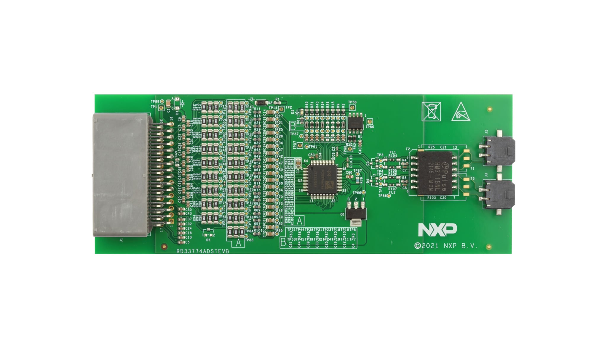
The RD33774ADSTEVB serves as a hardware evaluation tool in support of NXP's MC33774A device. The MC33774A is a battery-cell controller that monitors up to 18 lithium-ion battery cells. RD33774ADSTEVB is designed for use in automotive and industrial applications.
The device performs analog-to-digital conversion on the differential cell voltages and currents. It is also capable of battery-charge coulomb counting and battery temperature measurements. The RD33774ADSTEVB can be used for rapid prototyping of MC33774A-based applications that involve voltage and temperature sensing.
2.3 Board Components
Overview of the RD33774ADSTEVB board
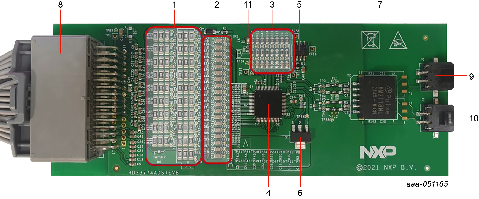
| Number | Name | Description |
|---|---|---|
| 1 | Cell balancing resistors | 3 x 33 ohms in parallel on each Cx pin: 200 mA of cell-balancing current @4.5 V |
| 2 | Cell terminal low-pass filters | LPF: 10 kΩ resistor/0.047 µF capacitor to GND |
| 3 | GPIO low-pass filters | For NTC connections and temperature measurement |
| 4 | MC33774A (U2) | 18-cell battery-cell controller IC |
| 5 | NV24C64DWVLT3G (U1) |
High-speed 64 Kb I2C EEPROM |
| 6 | NSS1C201MZ4T1G (Q1) |
NPN supply bipolar transistor |
| 7 | HM2118NL or HM2168NL(T2) or capacitive coupling |
Default BOM: High-voltage dual-channel transformer |
| 8 | JAE-MX34032NF2 (J1) |
32-pin connector for cell connections and NTC connections |
| 9 | MOLEX-43650-0213 (J2) |
TPL connector to higher node |
| 10 | MOLEX-43650-0213 (J3) |
TPL connector to lower node |
| 11 | LED | VAUX status |
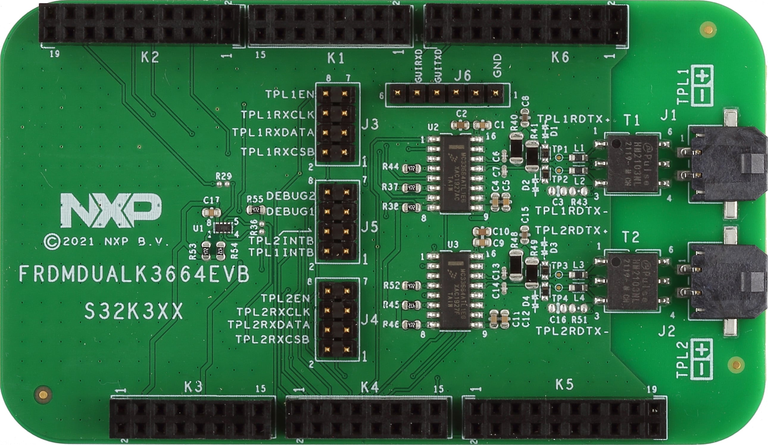
3. Configure Hardware
The RD33774ADSTEVB kit is designed for use with the FRDMDUALK3664EVB or a FRDM665SPIEVB in high-voltage isolated applications that provide an SPI-to-high-speed isolated communication interface. The FRDMDUALK3664EVB includes two MC33664 isolated-network high-speed transceivers allowing loopback connection. MCU SPI data bits are directly converted to pulse bit information.
The FRDM665SPIEVB includes one MC33665A isolated-network high-speed transceiver allowing loopback connection. MCU SPI data bits are directly converted to pulse bit information.
3.1 Battery Emulator Connection
The RD33774ADSTEVB supports the use of a battery-cell emulator, such as the BATT-18EMULATOR board.
The BATT-18EMULATOR is an 18-cell battery-emulator board that provides an intuitive way to change the voltage across any of the 18 cells and four voltage outputs in order to emulate four external NTCs. The emulator board can be connected to the RD33774ADSTEVB J1 connector using the provided cell connection cable.
Up to three RD33774ADSTEVB can be connected to one BATT-18EMULATOR. See Figure 2


Design Resources
Additional References
In addition to our MC33774, 18 Channel Li-Ion Battery Cell Controller IC ASIL D page, you may also want to visit: