Getting Started with the RD-BESS1500BUN
Contents of this document
-
Out of the Box
-
Get Hardware
-
Configure Hardware
Sign in to save your progress. Don't have an account? Create one.
Purchase your RD-BESS1500BUN
1. Out of the Box
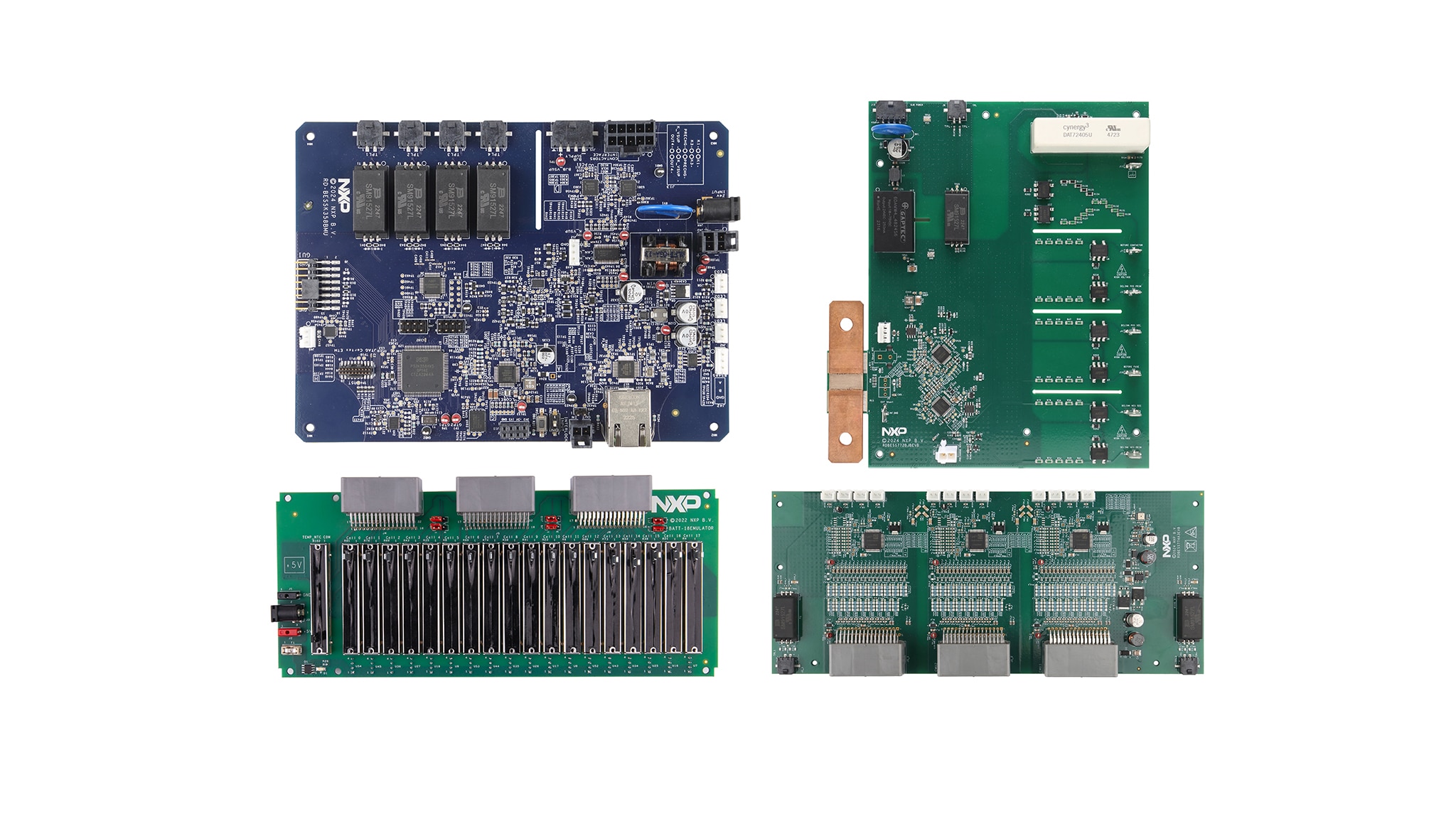
The RD-BESS1500BUN is an electrical transport protocol link (ETPL) based battery energy storage system (BESS) reference design bundle for 1500 V applications. This bundle has been designed for evaluation and development purposes. The RD-BESS1500BUN is composed of a hardware kit and several software packages.
This document details the first startup steps to visualize the measurements performed by the system in a graphical user interface (GUI).

1.1 Kit Content and Packing List
The RD-BESS1500BUN bundle contains the following items:
- Battery management unit (BMU)
- One RD-BESSK358BMU board
- One power supply (24 V DC, 3.75 A)
- One power cord
- One ETPL cable
- One RS-485 cable
- One Ethernet cable
- One controller area network (CAN) cable
- One interlock cable
- One contactors cable
- One secure element antenna
- One USB to RS-485 converter
- Cell monitoring unit (CMU)
- One RDBESS774A3EVB board
- Three supply cables
- One ETPL cable
- Battery junction box (BJB)
- One RDBESS772BJBEVB board
- One power cord
- Six high-voltage measurement cables
- Two thermal sensor cables
- One chassis cable
- One GND cable
- Two Hall sensor cables
- One ETPL cable
- One plexiglass cover
- Battery emulation kit
- One BATT-18EMULATOR board
- One power supply (5 V DC, 5 A)
- Links to the software and safety kits
1.2 Additional Hardware
In addition to the kit contents, the following hardware is beneficial when working with this kit.
- A PC, to run the provided GUI and program the RD-BESSK358BMU board
- A Joint Test Access Group (JTAG) debugger to program the RD-BESSK358BMU board. The recommended debugger is PEmicro multilink FX
1.3 Software
In addition to the kit contents, the following software is beneficial when working with this kit.
- BMS monitor GUI V1.0 for measurement visualization and actuators control
2. Get Hardware
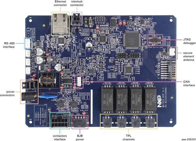
2.1 BMU Features
The BMU is the control part of the BESS. The BMU processes the data, decides, and commands the system.
The RD-BESSK358BMU is the BESS reference design BMU for 1500 V applications. This BMU kit includes a power supply and five cables to interface with other parts of the BESS.
To learn more about the RD-BESSK358BMU, visit the website associated with this reference design, or read its user manual.
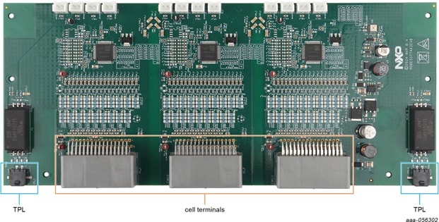
2.2 CMU Features
The CMU is the cell-sensing part of the battery management system (BMS). The CMU precisely monitors cell voltages and environmental temperatures to ensure safe battery operation. The CMU also enables fast cell‑balancing.
The RDBESS774A3EVB is the BESS reference design CMU for ETPL-based architectures based on the MC33774A battery cell controller. This CMU kit includes four cables to interface with other parts of the BESS.
To learn more about the RDBESS774A3EVB, visit the website associated with this reference design, or read its user manual.
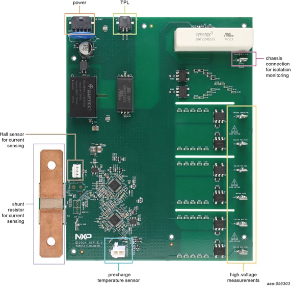
2.3 BJB Features
The BJB is the pack-level sensing part of the BESS. The BJB measures high voltages. This measurement allows monitoring the connections of the contactors to the inverter and the charger. The BJB also precisely measures the system current and monitors the battery to chassis isolation.
The RDBESS772BJBEVB is the 1500 V BESS reference design BJB for ETPL-based architectures. This BJB kit includes 11 cables to interface with other parts of the BESS.
To learn more about the RDBESS772BJBEVB, visit the website associated with this reference design, or read its user manual.
3. Configure Hardware
3.1 Configure the Hardware
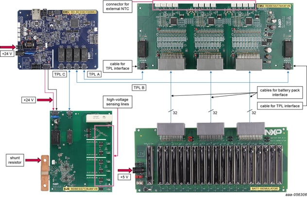
To connect and power up the system, complete the following steps.
- 1. Unpack all boards and cables from the kit
- 2. Connect the power cord to the RD-BESSK358BMU
(J44) - 3. Connect the controller area network flexible data rate (CAN FD) cable to the RD-BESSK358BMU
(J12) - 4. Connect the contactor cable to the RD-BESSK358BMU
(J13) - 5. Connect the interlock cable to the RD-BESSK358BMU
(J14) - 6. Connect the CMU
- 6.1 Connect the first ETPL cable to the RD-BESSK358BMU
(J2)and the RDBESS774A3EVB(J2_1) - 6.2 Connect the second ETPL cable to the RD-BESSK358BMU
(J3)and the RDBESS774A3EVB(J2_3)
- 7. Connect the BJB
- 7.1 Connect the ETPL cable between the RD-BESSK358BMU
(J4)and the RDBESS772BJBEVB(J9) - 7.2 Connect the BJB supply cable between the RD-BESSK358BMU
(J15)and the RDBESS772BJBEVB(J12)
Design Resources
Additional References
In addition to the RD-BESS1500BUN, 1500 V battery energy storage reference design page, visit: