Getting Started with the P3T1035XUK-ARD Evaluation Board
Contents of this document
-
Out of the Box
-
Get to Know the Hardware
-
Install Software
-
Configure Hardware
Sign in to save your progress. Don't have an account? Create one.

Purchase your P3T1035xUK Arduino® Shield Evaluation Board
1. Out of the Box
The NXP analog product development boards provide an easy-to-use platform for evaluating NXP products. The boards support a range of analog, mixed-signal and power solutions. They incorporate monolithic integrated circuits and system-in-package devices that use proven high-volume technology. NXP products offer longer battery life, a smaller form factor, reduced component counts, lower cost, and improved performance in powering state-of-the-art systems.
This page will guide you through the process of setting up and using the P3T1035XUK-ARD board.
1.1 Kit Contents and Packing List
The P3T1035XUK-ARD kit contents include:
- Assembled and tested evaluation board in an antistatic bag
1.3 Static Handling Requirements
This device is sensitive to ElectroStatic Discharge (ESD). Therefore care should be taken during transport and handling. You must use a ground strap or touch the PC case or other grounded source before unpacking or handling the hardware.
1.4 Minimum System Requirements
- PC Pentium processor (or equivalent)
- One USB port (either 3.0 or 2.0 or 1.1 compatible)
- Windows 7, 8, or 10
- OM13089 MCU board (from www.nxp.com)
2. Get to Know the Hardware
2.1 Board Features
- A complete evaluation platform for the P3T1035XUK I³C, I²C-bus, 0.5 °C accuracy, digital temperature sensor
- Easy to use GUI based software demonstrates the capabilities of the P3T1035XUK
- On-board temperature sensor for system thermal management experiments
- Convenient test points for easy scope measurements and signal access
- USB interface to the host PC
- Power supply from USB port (x2) or external power supply can be used to power P3T1035XUK-ARD evaluation board
2.2 Board Description
The P3T1035XUK-ARD evaluation board features an I³C, I²C-bus, 0.5 °C accuracy, digital temperature sensor. A graphical interface allows the user to easily explore the different functions of the driver. The board can be connected in parallel with other I²C-bus demo boards to create an evaluation system
3. Install Software
3.1 Install P3T1035XUK-ARD Demo GUI
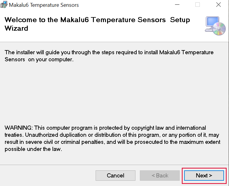
- Double click on “setup.exe” to install P3T1035XUK-ARD demo GUI
-
Click “Next” button three times to complete installation
3.2 Run Makalu6 Temperature Sensors GUI on Windows 7,8,10 PC
-
Double click on “Makalu6 Temperature Sensors” icon to start GUI.

-
Select proper COM port (last COM port normally) and click “Connect” button to connect MIMXRT685-EVK board.

-
Use Setting tab to select I²C and I³C-bus speed, and click on the “Set Speed” button.

-
Click on “Scan” button to discover any NXP temperature sensor target address on the evaluation board.

-
Use Sensor Type to select which temperature sensor to be tested on the evaluation board.

-
Read/Write configuration register in the temperature sensor device control tab.

-
Read/Set THIGH (high limit) and TLOW (low limit) registers in the temperature sensor device control tab.

-
Perform one-shot or polling temperature read in the temperature sensor device control tab.

-
Read internal registers into a file or read a file into the internal registers in the in the temperature sensor device control tab.

-
Perform I³C general tests in the I³C tab.

-
Perform I²C general tests in the I²C tab.

4. Configure Hardware
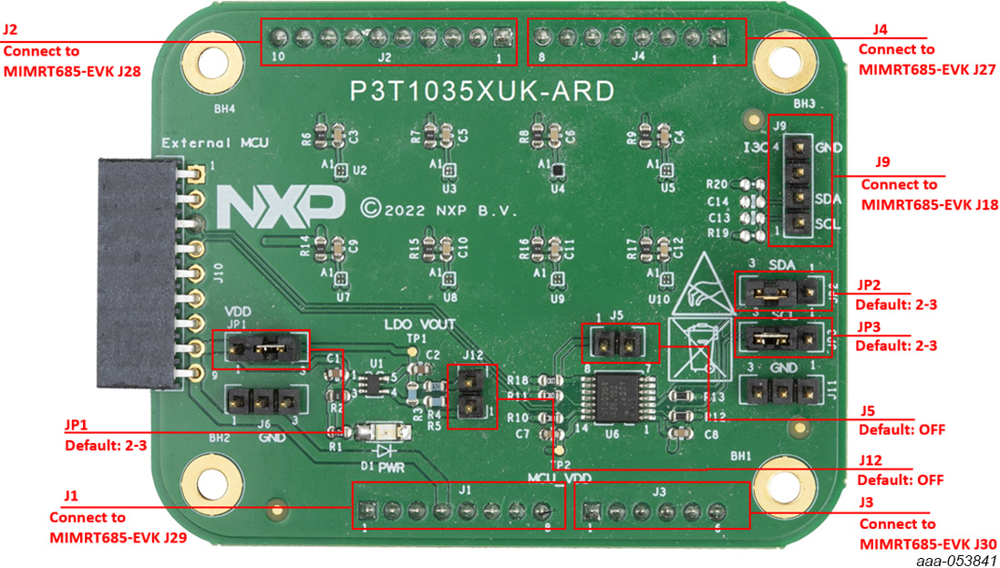
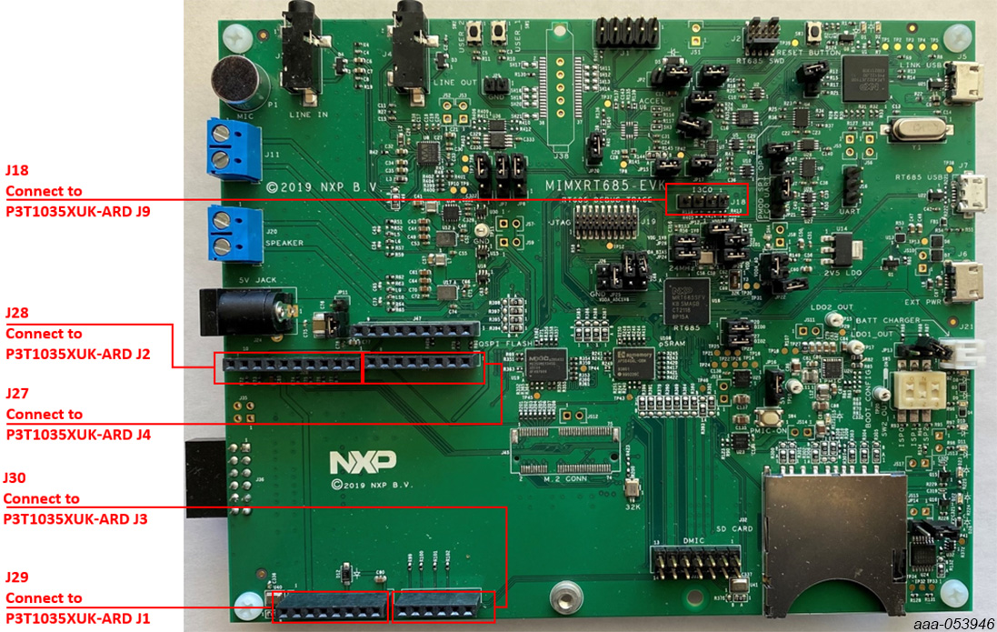
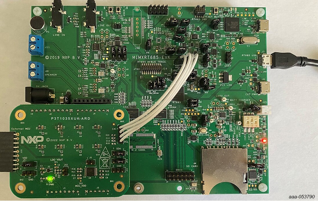
4.1 Configure the Hardware
P3T1035XUK-ARD EV board and MIMXRT685-EVK MCU board connection
P3T1035XUK-ARD evaluation board is connected to the MIMXRT685-EVK MCU board using four connectors (J1/J2/J3/J4 on P3T1035XUK-ARD board and J27/J28/J29/J30 on MIMXRT685-EVK board) for I²C-bus and power supply, and one connector (J9 on P3T1035XUK-ARD board and J18 on MIMXRT685-EVK board) for I³C-bus.
The MIMXRT685-EVK MCU board communicates with P3T1035XUK demo GUI through PC USB port and uses I²C or I³C-bus to communicate to P3T1035XUK.
Design Resources
Additional References
In addition to our P3T1035xUK, I³C, I²C-Bus, ±0.5 °C Accuracy, Digital Temperature Sensor page, you may also want to visit: