Getting Started with the OM40000
Contents of this document
-
Plug It In!
-
Get Software
-
Build, Run
Sign in to save your progress. Don't have an account? Create one.

Purchase your LPCXpresso802 for the LPC802 family of MCUs
Plug It In!
Let's take your LPCXpresso802 board for a test drive! You have the choice of watching the sequence in a short video or following the detailed actions list below.
Get Started with LPCXpresso802 Development Platform - Demo
1.1 Install drivers
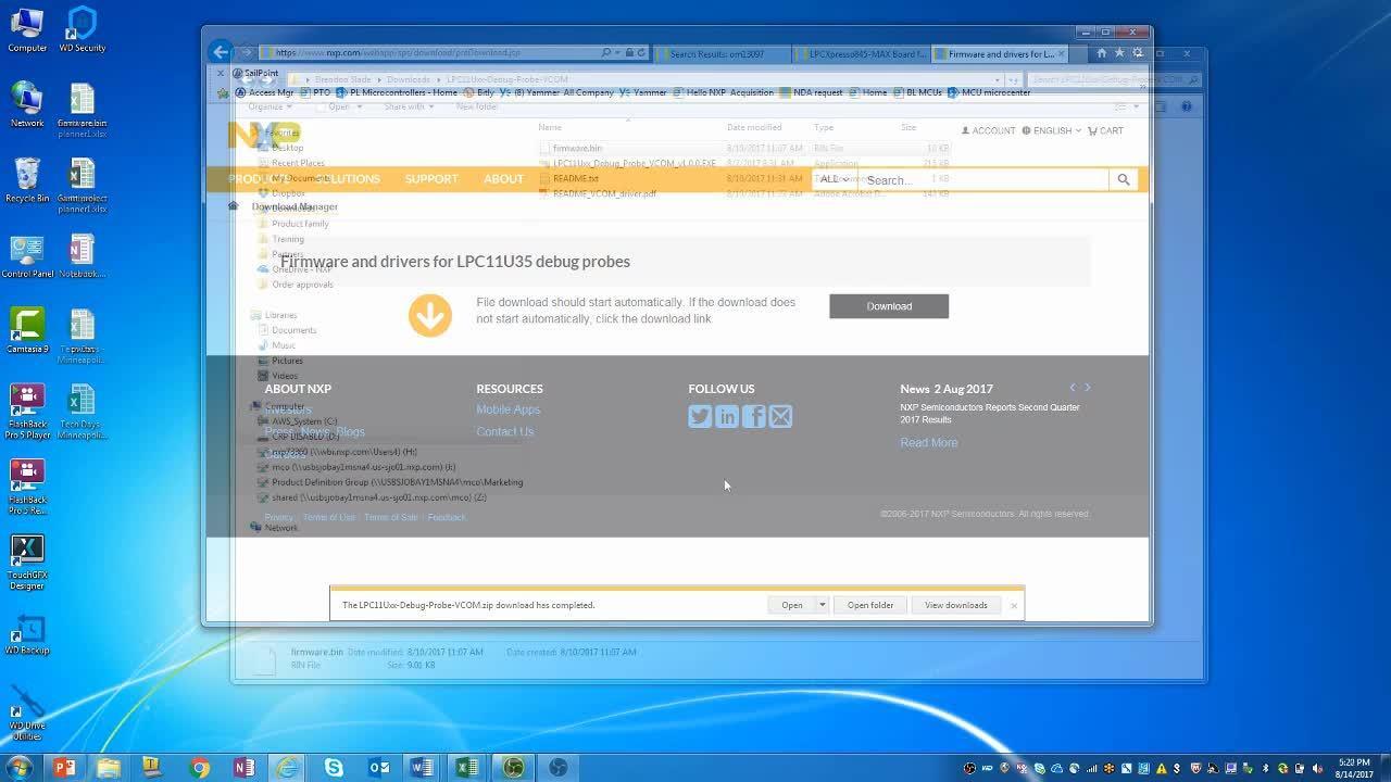
On windows 7 or 8 platforms, before using your board it is recommended that you install the VCOM device driver. Start by downloading the firmware and driver package and from here
1.2 Plug in the board
Using the supplied micro USB cable, connect CN1 on the board to a host computer. The demo code will then run; the "face" made from LEDs on the snap-off section of the board will light up:
- The outer ring of red LEDs will vary in brightness, based on the temperature of the LM75 sensor (U7) on the board. Press your finger on U7 to see the LEDs get brighter.
- The "mouth" of the LED face (green LEDs) will alternate through a sad, happy and surprised expression. The speed at which the mouth changes will depend on the position of the potentiometer adjacent to the LED face. You can use the supplied screwdriver to adjust this.
Get Software
2.1 Jump Start Your Design with the Code Bundles
LPC8xx Family Code Bundles are easy to understand drivers and examples, with full source code provided.
Get Code for LPC81x
Get Code for LPC82x
Get Code for LPC83x
Get Code for LPC84X
2.2 Install your toolchain
NXP offers a free, GNU/Eclipse based toolchain called MCUXpresso IDE.

Want to use a different toolchain?
No problem! Code Bundles are also available for IAR and Keil.

2.3 Serial terminal
Some Code Bundle UART examples set up for IAR and Keil tools use the MCU UART for print output, and this is also an option for the MCUXpresso IDE. If you are not sure how to use a terminal application try one of these tutorials:
Not sure how to use a terminal application? Try one of these tutorials:
2.4 Tera Term Tutorial
Tera Term is a very popular open source terminal emulation application. This program can be used to display information sent from your NXP development platform's virtual serial port.
- Download: Tera Term from SourceForge. After the download, run the installer and then return to this webpage to continue.
- Launch: Tera Term. The first time it launches, it will show you the following dialog. Select the serial option. Assuming your board is plugged in, there should be a COM port automatically populated in the list.
- Configure: the serial port settings (using the COM port number identified earlier) to 115200 baud rate, 8 data bits, no parity and 1 stop bit. To do this, go to Setup -> Serial Port and change the settings.
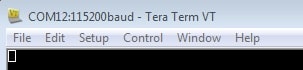
- Verify: that the connection is open. If connected, Tera Term will show something like below in it's title bar.
- You're ready to go

2.5 PuTTY Tutorial
PuTTY is a popular terminal emulation application. This program can be used to display information sent from your NXP development platform's virtual serial port.
- Download: PuTTY using the button below. After the download, run the installer and then return to this webpage to continue.
- Launch: PuTTY by either double clicking on the
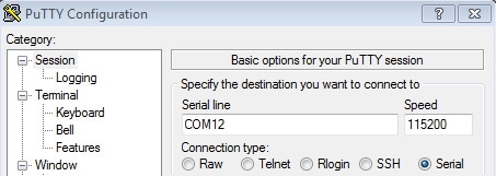
*.exefile you downloaded or from the Start menu, depending on the type of download you selected. - Configure: In the window that launches, select the Serial radio button and enter the COM port number that you determined earlier. Also enter the baud rate, in this case 115200.
- Click Open: to open the serial connection. Assuming the board is connected and you entered the correct COM port, the terminal window will open. If the configuration is not correct, PuTTY will alert you.
- You're ready to go
Build, Run
Note that MCUXpresso IDE (version 10.1 or later) has built-in knowledge of the LPC802 part family, so does not require any SDK installation steps. Follow the steps below to build and run a simple example from the LPC802 Code Bundles provided by NXP. Code Bundles for the LPC8xx family are included in the MCUXpresso IDE installation. These can also be downloaded from nxp.com (in case of any updates between IDE releases): https://www.nxp.com/LPC800-Code-Bundles. (Note that MCUXpresso IDE has a link to the Code Bundle Page in the Help -> Additional Resources menu).
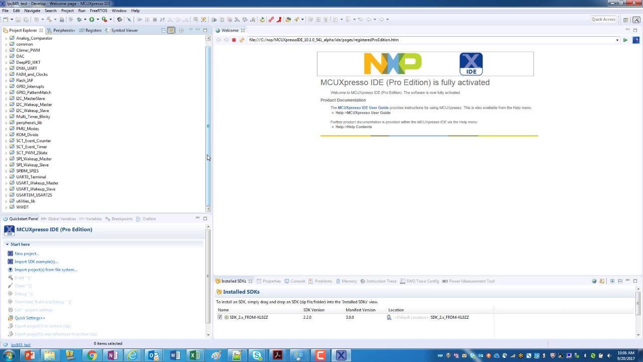
- Open a new workspace in the IDE.
- In the Quickstart panel of the IDE, click in "Import project(s) from the file system".
- In the "Import project(s) from file system..." dialog box that opens, click "Browse..." in the Project Archive (from zip) section, and select the LPC802 Code Bundle zip file from the Code Bundles directory in the MCUXpresso IDE installation (or select a version downloaded from nxp.com, as described in Step 1 above.) Click "Next >" on the "Import project(s) from file system..." dialog to continue.
- You will see several projects listed in the Code Bundle; click "Finish" to import them all.
- The dialog box will close, and you will see the imported projects in the Project tab at the upper left window of the IDE. Click on Example_Multi_Timer_Blinky to select it, then select Build from the Quickstart panel. You will see the build processing in the Console window to the right of the Quickstart panel. The projects are set up to include dependency checking, so the build process will automatically build the utility and peripheral libraries as well as the example program.
- 6. Ensuring the LPCXpresso802 is connected to the host computer, click Debug in the Quickstart panel. The IDE will search for available debug probes. Select the debug probe that appears for your board, then click OK. Note that the IDE will remember your selection for the next time you debug this project, so will not prompt for this again, unless it cannot find the board.
- The code will execute to main. Press F8 to resume and run the program. You will now see the User LEDs light, each color in turn.
Building and debugging with MCUXpresso IDE