Getting Started with the FRDMPT2001EVM
Contents of this document
-
Get Started
-
Board Features
-
Configure Hardware
-
Graphical User Interface
-
Configuring SPIGen Software
-
Success
Sign in to save your progress. Don't have an account? Create one.

Purchase your PT2001 Evaluation Board
1. Get Started
The NXP analog product development boards provide an easy-to-use platform for evaluating NXP products. The boards support a range of analog, mixed-signal and power solutions. They incorporate monolithic integrated circuits and system-in-package devices that use proven high-volume technology. NXP products offer longer battery life, a smaller form factor, reduced component counts, lower cost and improved performance in powering state-of-the-art systems.
This page will guide you through learning about how to set up the FRDMPT2001EVM board.
1.1 Kit Contents/Packing List
The FRDMPT2001EVM contents include:
- Assembled and tested FRDMPT2001EVM board mounted to a FRDM-KL25Z board in an anti-static bag
- Quick start guide
- Warranty card
1.2 Required Equipment
To use this kit, you need:
- 1/8” blade screwdriver for connecting the loads
- DC power supply: 12 V with minimum 5.0 A current handling capability, depending on load requirements
- USB Standard A (male) to micro-B (male) cable (for included K144 FRDM board)
- USB Standard A (male) to mini-B (male) cable (for KL25Z FRDM board)
- Typical loads (direct injection fuel injectors)
- FRDM-KL25Z FRDM Development Platform for SPI communication
- NXP SPIGen software (for use with FRDM-KL25Z based SPI Dongle)
- NXP's S32 Design Studio software (for use with the S32K144EVB-Q100)
- NXP's PT2001 Developer Studio (for use with the FRDMPT2001EVM)
2. Board Features
2.1 Board Features
- PT2001 direct injection predriver integrated circuit
- external MOSFETs
- power-conditioning circuitry
- +12 V to +36 V VSUPP power to the PT2001
2.2 Board Descriptions
The FRDMPT2001EVM consists of two boards:
Two options are provided for the MCU companion:
- FRDM-KL25Z board (default configuration) allows the developer to use NXP’s SPIGen software to directly access the PT2001 on the FRDMPT2001EVM board. This also allows the developer to be quickly familiar with PT2001 without having the need to write any MCU code.
- S32K144EVB-Q100 board, this kit includes the MCU S32K144 an automotive Kinetis processor which offers the high-speed performance required to evaluate PT2001 automotive fuel system designs. NXP’s S32 Design Studio software serves as the platform for developing application-specific MCU code and downloading it to the S32K144EVB-Q100 through the OpenSDA port.
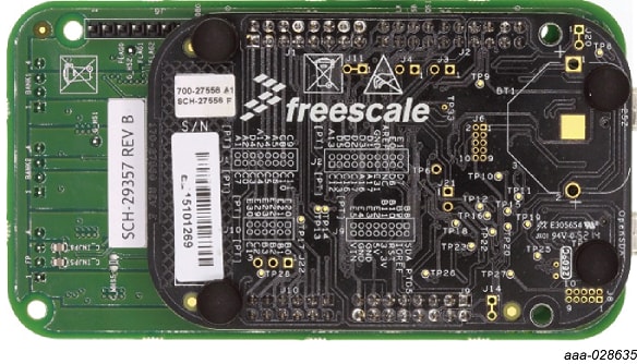
2.3 Board Image
The FRDMPT2001EVM serves as the interface between the PT2001 and the components it controls. The board contains a commercial version of the PT2001 and connectors for up to four fuel injectors, two fuel pumps and a DC/DC converter.

2.4 Additional Board Support
Board block diagram, board description, test points and additional board descriptions and images are available in the User Guide. Refer to FRDMPT2001EVM evaluation board.
3. Configure Hardware
The FRDM-KL25Z evaluation board was chosen specifically to work with the FRDMPT2001EVM kit because of its low cost and features. The FRDM-KL25Z boardmakes use of the USB, built in LEDs and I/O ports availablewith NXP’s Kinetis KL2x family of microcontrollers.
The FRDMPT2001EVM connects to the FRDM-KL25Z using the four-dual row ArduinoTM R3 connectors on the bottom of the board. The procedure for configuring the FRDMPT2001EVM for use with the FRDM-KL25Z is as follows:
- Detach the S32K144EVB-Q100 from the FRDMPT2001EVM board.
- Place connector blocks on the outer rows of all four Arduino connectors on the FRDMKL25Z.
- Attach the FRDM-KL25Z under FRDMPT2001EVM board such that connector J3 on the FRDMPT2001EVM aligns with connector J9 on the FRDM-KL25Z and connector J2 on the FRDMPT2001EVM aligns with connector J2 on the FRDM-KL25Z.
3.1 Configuration Image
To run the examples included in the software bundle, the following connections and setup must be performed:
- Make sure SPIGen 7.0 (or higher) is installed on the PC and it can communicate with the FRDM board FRDM-KL25Z. A blue LED, lights on the FRDM-KL25Z when SPIGen is running and the board is properly connected
- Connect the FRDM-KL25Z to the PC using the USB KL25Z port (left side of SW1). The USB_PWR LED on the FRDMPT2001EVM should be illuminated
- With the power supply switched off, attach the +12 VDC supply to the VSUPP input connector on the FRDMPT2001EVM. Make sure that the power supply is connected to the correct GND and +12 V terminals on the board. The current capability of the +12 V supply must exceed the maximum total current required by the number of loads that can be simultaneously ON
- Attach loads (Injectors) to the INJ1, INJ2, INJ3, INJ4, INJ5 and INJ6 output terminals as desired
- Turn on the +12 V supply. The +5.0 V LED illuminates, indicating that the board is properly connected.

3.2 Connect USB Cable
Connect the Standard-A plug of the USB cable to the host PC. Connect the mini-B plug on the cable to the port labeled USBKL25Z on the FRDM-KL25Z.
3.3 Additional Board Support
Detailed configuration and images are available in the User Guide. Refer to FRDMPT2001EVM evaluation board for additional details.
4. Graphical User Interface
4.1 Graphical User Interface
Download and run SW for the FRDMPT2001EVM
- Go to the P&E Microcomputer Systems OpenSDA page at http://www.pemicro.com/opensda and in the OpenSDAFirmware (MSD and Debug) box, click to download the Firmware Apps zip file.
- When the download completes, unzip the file contents to a folder on the host PC.
- Connect the Standard A plug of the USB cable to the host PC.
- On the FRDM-KL25Z, press and hold down the Reset button. With the button held down, attach the mini-B plug of the USB cable to the FRDM-KL25Z USB port labeled SDA. Then release the Reset button. A blinking LED indicates the board is in Bootloader mode.
- Open Windows Explorer on the host PC. An icon labeled BOOTLOADER appears as a removable drive on the PC.
- From the files extracted from the PEMicro zip file, locate the driver file named MSDDEBUG-FRDM-KL25Z_Pemicro_v118.SDA. Drag and drop this file onto the BOOTLOADER icon.
- Unplug the USB mini-B plug then re-insert the plug back into the SDA port. A blinking LED on the board indicates that the FRDM-KL25Z is in bootloader mode.
- Locate the SPIGEN UsbSpiDongleKL25Zv507.srec image folder in the SPIGEN folder (C:\Program Files (x86) \SPIGen\SPI Dongle Firmware).
- Copy and paste or drag and drop the. srec file to the FRDM-KL25Z removable drive icon on the host PC.
- Unplug the USB cable from the FRDM-KL25Z SDA port.
5. Configuring SPIGen Software
5.1 Configuring SPIGen Software
- In the Windows Start menu, go to Programs -> SPIGen and click the SPIGen icon. This icon appears on the Windows desktop if the appropriate option is selected during installation.
- When the SPIGen Graphical User Interface (GUI) appears, go to the file menu in the upper-left corner and select Open. A file selection window opens. In the bottom-right corner of the window, the drop-down box value should be set to SPIGen Files (*.spi). If the configuration file name has a .txt extension, set this value to All Files (*.*).
- Browse for the SPIGen configuration file downloaded from the tool summary page (see Section 6.1.1 "Installing SPIGen on the host PC"). Select the configuration file and click Open. SPIGen creates a SPI command generator configured specifically for the FRDMPT2001EVM board. The GUI is shown in Figure 6. The text at the top is the name of the configuration file that is loaded. The left side panel displays folders that group user interfaces. The interfaces in the pre-installed PT2001 folder pertain specifically to the board FRDMPT2001EVM. When the configuration file loads, SPIGen is assigned a FRDMPT2001EVM specific list of Extra Pins and Quick Commands.

5.2 Complet Step by Step
Complete step by step software and hardware instructions are Detailed in the User Guide. Additionally, enabling the S32K144 board instructions and S32 design studio and microcode are included. Refer to FRDMPT2001EVM evaluation board.
6. Success
Now start embedded application development.
6.2 Tool Summary Page
The overview tab provides an overview of the device, product features, a description of the kit contents, a list of (and links to) supported devices, list of (and links to) any related products and a Get Started section.
- On the Overview tab, locate the Jump To navigation feature on the left side of the window.
- Select the Get Started link, review each entry and download an entry by clicking on the title.
-
After reviewing the Overview tab, visit the other
product-related tabs for additional information:
- Documentation: download current documentation.
- Software and Tools: download current hardware and software tools / Drivers.
- Buy/Parametrics: purchase the product and view the product parametrics.
- Build package: the bill of materials (BOM) and supporting schematics are also available for download in the Get Started section of the Overview tab.
6.3 For the Entire Solution
in addition to our PT2001 Programmable Gate Driver for Solenoid Control page you may also want to visit:
- Product pages: FRDM-KL25Z page S32K144EVB page
- Support page: P&E Microcomputer Systems OpenSDA page at http://www.pemicro.com/opensda
- Application pages: Diesel Engine Management Gasoline Engine Management
- Hardware pages: Analog Toolbox
- Software pages: Analog Expert Software and Tools