- Analog Toolbox
- Getting Started with the FRDM-HB2002ESEVM
Getting Started with the FRDM-HB2002ESEVM
Contents of this document
-
Out of the Box
-
Get Hardware
-
Configure Hardware
-
Get Software
Sign in to save your progress. Don't have an account? Create one.

Purchase your FRDM Kit for HB2002, Programmable Brushed DC Motor Control in QFN
1. Out of the Box
The NXP analog product development boards provide an easy-to-use platform for evaluating NXP products. The boards support a range of analog, mixed-signal and power solutions. They incorporate monolithic integrated circuits and system-in-package devices that use proven high-volume technology. NXP products offer longer battery life, a smaller form factor, reduced component counts, lower cost and improved performance in powering state-of-the-art systems.
This page will guide you through the process of setting up and using the FRDM- HB2002ESEVM evaluation board.
1.1 Kit Contents and Packing List
The FRDM-HB2002ESEVM contents include:
- Assembled and tested FRDM-HB2002ESEVM in an anti-static bag
- USB standard A (male) to mini-B (male) cable
- Quick start guide
1.2 Additional Hardware
In addition to the kit contents, the following hardware is necessary or beneficial when working with this kit.
- DC power supply: 5.0 V to 40 V with up to 20 A current handling capability, depending on motor requirements
- 3/16-inch blade screwdriver for connecting the cables
- Typical loads (brushed DC motor, power resistors or inductive load with up to 5.0 A and 28 V operation)
- Function generator (optional)
1.3 Windows PC Workstation
This evaluation board requires a Windows PC workstation. Meeting these minimum specifications should produce great results when working with this evaluation board.
- USB-enabled computer with Windows 7, Windows 8, or Windows 10
1.4 Software
Installing software is necessary to work with this evaluation board. All listed software is available on the evaluation board's information page at FRDM Kit for HB2002, Programmable Brushed DC Motor Control in QFN.
- SPI Generator (SPIGen) software, version 7.1.8 or later, a Graphical User Interface (GUI)
2. Get Hardware
2.1 Board Features
- Built-in reverse battery protection
- Test points that allow signal probing
- Built-in voltage regulator to supply logic level circuitry
- Current feedback network for real-time load current monitoring by MCU ADC
- LEDs to indicate the supply status and the direction of the motor
- Low ESR capacitor to reduce ripple in the power supply
- TVS protection diode to handle system level transients
2.2 Board Description
The FRDM-HB2002ESEVM evaluation kit exercises all the functions of the MC33HB2002 H-bridge device. Lab equipment or any MCU with GPIOs can control the parallel inputs to provide PWM control to the inputs.
The board can be used with a FRDM-KL25Z board connected to a USB port of a PC. Configure, control and monitor the status of MC33HB2002 by using the SPI communication capabilities of the board.
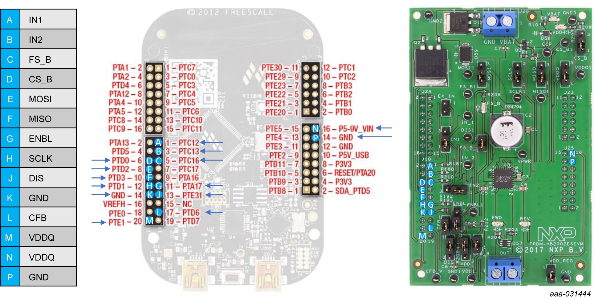
2.3 Board Components
Overview of the FRDM-HB2002ESEVM evaluation board
- MC33HB2002ES
- Power connector
- Reverse battery protection
- 5.0 V regulator
- Jumpers
- Test points
- Output connector

| Label | Name | Description |
| 1 | MC33HB2002ES | monolithic H-bridge motor driver IC in a robust, thermally enhanced 28-pin HVQFN (6 × 6 mm) package |
| 2 | Power and ground inputs | power supply terminal to connect the battery/power supply with the board |
| 3 | Reverse battery protection | MOSFET for protecting MC33HB2002 in reverse battery condition |
| 4 | 5.0 V regulator | monolithic H-bridge motor driver IC in a robust, thermally enhanced 28-pin HVQFN (6 × 6 mm) package |
| 5 | Jumpers | jumpers for configuring the board for different modes of operation |
| 6 | Test points | test points to probe different signals |
| 7 | Output terminal | output connector to connect a load to the MC33HB2002 output |
3. Configure Hardware
The FRDM-HB2002ESEVM consists of an H-bridge, a parallel and SPI interface, power conditioning circuitry and a FRDM-KL25Z board. The board can be configured for use with a FRDM-KL25Z board or a function generator.
When using the FRDM-HB2002ESEVM, make sure that the maximum motor supply voltage (VPWR) stays within the 5.0 V to 40 V range. Operating outside this range may cause damage to the board.
3.1 Configuring the Hardware for Use with a FRDM-KL25Z
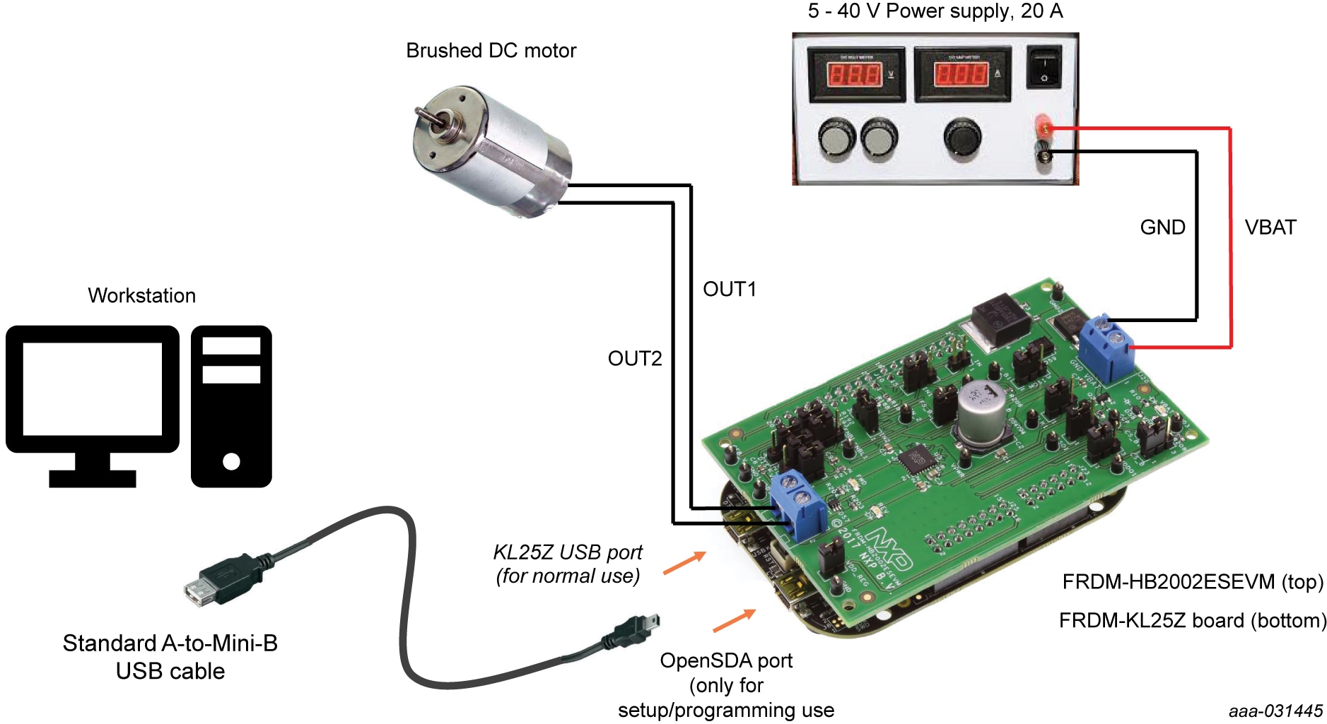
To configure the FRDM-HB2002ESEVM for use with the FRDM-KL25Z do the following:
- Connect the FRDM-HB2002ESEVM to the FRDM-KL25Z using the Arduino connectors on each board
- Connect the USB cable (not supplied with the kit) between the PC and the KL25Z USB port on the FRDM-KL25Z board
- With the power switched off, attach the DC power supply to the VBAT and GND screw connector terminal
J20on the evaluation board - Connect the load to the screw terminal
J21
3.2 Configuring the Hardware for Use with a Function Generator
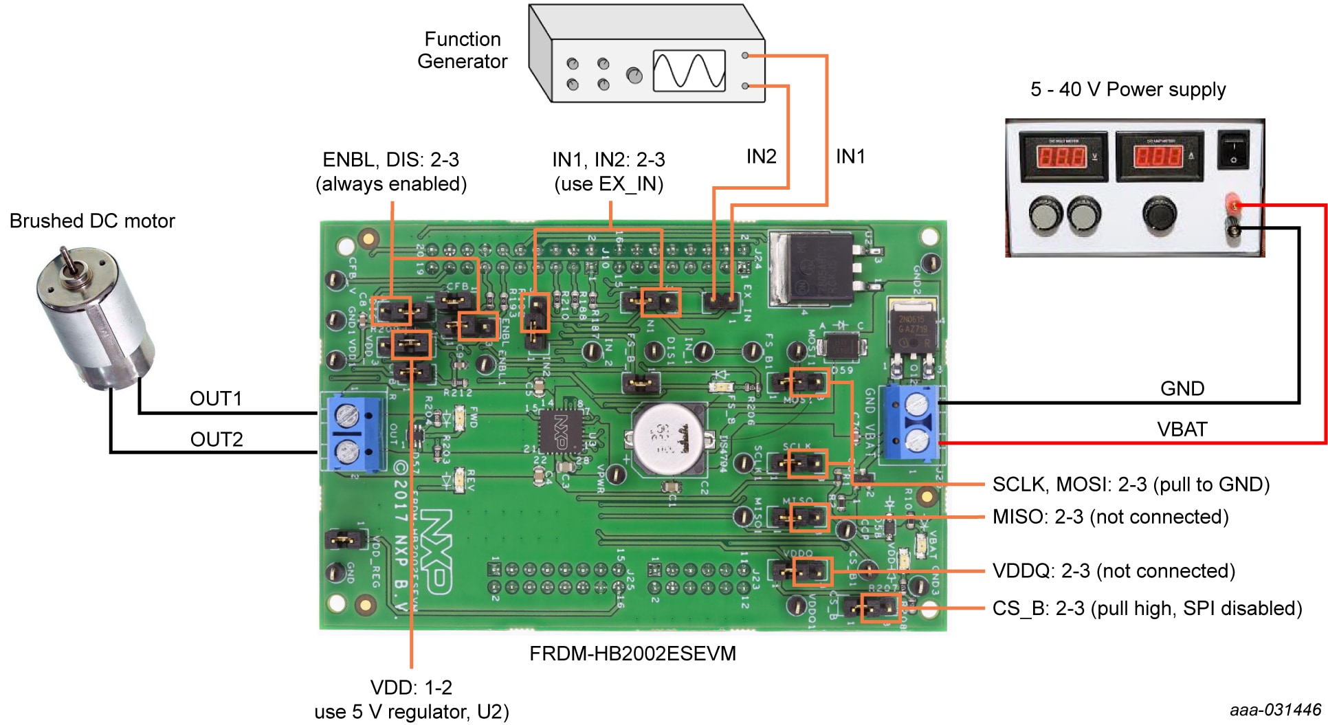
This section describes how to configure the FRDM-HB2002ESEVM for use with a function generator. The same connections apply if the board is connected to a microcontroller instead of a function generator.
- Connect the function generator to the EX_IN jumper, with one channel attached to each pin
- Change the board jumper connections
- With the power switched off, attach the DC power supply to the VBAT and GND screw connector terminal
J20on the evaluation board - Connect the load to the screw terminal
J21
4. Get Software
4.1 Configuring the FRDM-KL25Z Microcode
By default, the FRDM-KL25Z with this kit has the required firmware to interface with the FRDM-HB2002ESEVB. In the event of a loss of functionality following a reset, reprogramming or corrupted data issue, the microcode may be rewritten per the following steps:
- To clear the memory and place the board in boot loader mode, hold down the reset button while plugging a USB cable into the OpenSDA USB port
- Verify that the board appears as a "BOOTLOADER" device and continue with step
- If the board appears as "KL25Z," you may go to step 6
- Download the Firmware Apps .zip archive from the PEmicro OpenSDA webpage OpenSDA Support. Validate your email address to access the files
-
Find the most recent MDS-DEBUG-FRDM-KL25Z_Pemicro_v***.SDA and copy/drag-and-drop into the
BOOTLOADER device
- a. Based on the boot loader version, this operation may only be possible from a Windows 7 device. Examine the boot loader version via the HTML page on the device
- Reboot the board by unplugging and replugging the connection to the OpenSDA port. Verify now that the device appears as a "KL25Z" device to continue
-
Download the product-specific firmware “UsbSPIDongleKL25Z_HB2000_HB2001_v512.srec” for HB2002 from the following
link: Firmware for HB2000 and HB2001 evaluation kits using FRDM-KL25Z
- a. The .srec file is a product/family-specific configuration file for FRDM-KL25Z containing the pin definitions, SPI/PWM generation code and pin mapping assignments necessary to interface with the FRDM-HB2002ESEVB
-
With the KL25Z still plugged through the OpenSDA port, copy/drag-and-drop the .bin file into
the KL25Z device memory. Once done, disconnect the USB and plug into the other USB port, labeled
KL25Z
- a. The device may not appear as a distinct device to the computer while connected through the KL25Z USB port, this is normal
-
The FRDM-KL25Z board is now fully set up to work with FRDM-HB2002ESEVB and the SPIGen GUI
- a. There is also no firmware stored on the FRDM-HB2002ESEVB board itself, only on the MCU FRDM-KL25Z
All uploaded firmware is stored in non-volatile memory until the reset button is hit on the FRDM-KL25Z. There is no need to repeat this process upon every power-up, and there is no loss of data associated with a single unplug event.
4.2 Installing SPIGen on your Computer
- Go to SPI Generator (SPIGen) Software
- Select the Download button to open the Downloads tab
- Select the Download button next to the software version
- Read and accept the NXP Semiconductor Software License Agreement, leading to the SPIGen Software - Windows Application page. The download begins automatically
- Run the downloaded installation program, and follow the provided installation instructions
Design Resources
Board Information
Refer to UM11144, FRDM-HB2002ESEVM evaluation board for additional details on the featured components and board configuration.
Additional Resources
Product Summary Page
The product summary page for HB2002 is at SPI-Programmable H-Bridge Brushed DC Motor Driver.
Tool Summary Page
The tool summary page for FRDM-HB2002ESEVM board is at FRDM Kit for HB2002, Programmable Brushed DC Motor Control in QFN.
The page provides overview information, technical and functional specifications, ordering information, documentation and software. The Get Started provides quick-reference information applicable to using the FRDM-HB2002ESEVM board, including the downloadable assets.
References
In addition to our HB2002: SPI-Programmable H-Bridge Brushed DC Motor Driver page, you may also want to visit:
Product pages:
- HB2000: SPI Programmable 10 A H-Bridge Brushed DC Motor Driver
- HB2001: SPI Programmable 10 A H-Bridge Brushed DC Motor Driver
Application pages:
- Active Suspension
- Braking and Stability Control
- Diesel Engine Management
- Electric Pumps
- Hybrid Electric Vehicle (HEV) Applications
- Motorcycle Engine Control Unit (ECU) and Small Engine Control
FRDM pages:
Hardware pages:
Software pages: