Getting Started with MR-CANHUBK344 Evaluation Board
Contents of this document
-
Out of the Box
-
Get Software
-
Plug It In
-
Run the Software
Sign in to save your progress. Don't have an account? Create one.

Purchase your S32K344 Evaluation Board for Mobile Robotics with 100BASE-T1 and Six CANFD
1. Out of the Box
This is a quick-start guide for MR-CANHUBK344. You will find the basic hardware setup steps plus the demonstration software which converts Ethernet to CAN and CAN to Ethernet using the IEEE 1722 ACF-CAN protocol.
Find additional code examples specific to mobile robotics applications, vehicle software stacks and associated RTOSs such as FreeRTOS, NuttX, PX4, Zephyr on the S32K344 evaluation board.
1.1 Application Introduction
This example code supports all six CAN ports and the 100Base Ethernet port. The 100BASE-T1 port has automatic mode detection enabled so no further adjustments are needed.
The following cables and adapters are included with the board:
-
Hardware
- MR-CANHUBK3 board
- DCD-LZ programming adapter board (giving access to a console UART)
- USB-UART adapter cable (attaches to DCD-LZ)
- Power adapter cables, including JST-JH to common red SY connector, barrel connector, XT-60 Lipo battery connector
- 6x CAN cables
- 6x CAN termination boards
- 1x T1 ethernet cable (using JST-GH connectors)
- Generic JST-GH cables for UART/SPI/I2C/customizing to your specific needs
- Small OLED display
- NFC antenna connected to secure element
-
Documentation and software
- Release notes
- Project.zip S32 Design Studio project file
2. Get Software
The file "Project.zip" is downloadable from the examples section of the S32K344 evaluation board page. The project file is compatible with S32 Design Studio version 3.4.
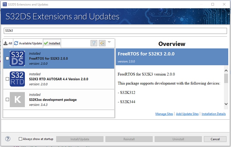
The following extensions are required to build the project:
- FreeRTOS for S32K3 2.0.0
- S32K3 RTD AUTOSAR® 4.4 Version 2.0.0
- S32K3xx development package Version 3.4.3
S32 Design Studio extension manager looks like the following screen.
Click on Add Update Sites link to add manually downloaded update site files:
2.1 Application
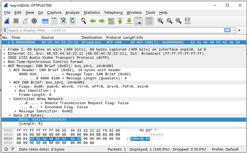
Once “MR_CANHUBK3_IEEE1722” has been successfully flashed on the MR-CANHUBK3 board, it will act as an ETH ↔ CAN IEEE 1722 protocol converter.
CAN messages received from CAN0 through CAN5 will be converted to an IEEE 1722 ACF-CAN fame and will be broadcasted to the Ethernet. To view incoming CAN frames you can install Wireshark on a Windows / Linux machine.
3. Plug It In
MR-CANHUBK344 board includes several interfaces. Necessary cables for all interfaces are provided with the kit. However, they may need to be cut or modified for your specific needs. This quick start guide assumes a familiarity with this type of hardware and the ability of making CAN, T1 Ethernet and power connections.
The demo also requires external components or test equipment that are able to make CAN/CAN FD interface connections and 100BASE-T1 Automotive Ethernet connections.
3.1 Power Input
Using a bench power supply or appropriate battery source, connect power 5 - 40 V (12 V nominal) @100 mA minimum to connector P27 at
the top left corner of the board (Pin 1-2 power, Pin 3 NC, Pin 4-5 ground) or use the next P28 connector (Pin 1 power, Pin 2 ground).
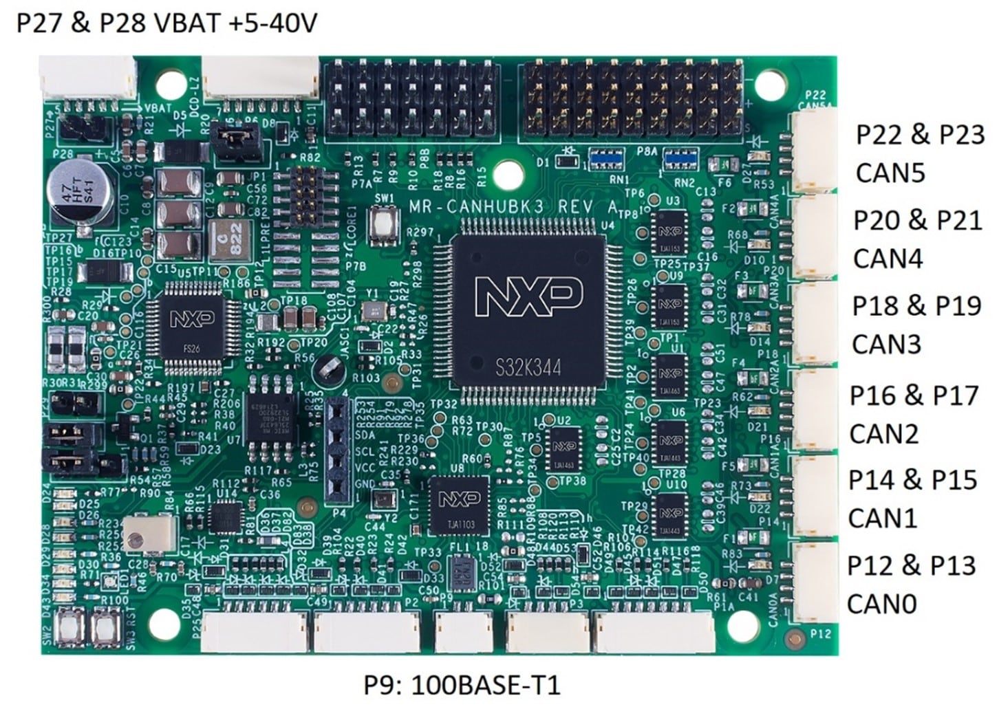
3.2 CAN Bus Connections
| pin # | Signal | Specification |
|---|---|---|
| 1 | 5V4 | 5.4V |
| 2 | CANx_H | 5.0V |
| 3 | CANx_L | 5.4V |
| 4 | GND | 0V |
A CAN bus typically requires termination at both ends. Use one of the included CAN-TERM termination boards when needed. Alternative CAN termination may be possible when using the ports that have the CAN SIC Phys.
3.3 100Base-T1 Ethernet Connection
The T1 connector (P9) is a 2 pin JST-GH connector for 2-wire 100Mbps Ethernet. The signals are capacitively coupled and are
polarized P and N. The TJA1003 T1 interface chip will auto-negotiate the polarity if it is reversed. You may adapt this cable to
other connector types as needed, by cutting the cable and soldering to the wires.
This JST-GH cable will connect directly to other mobile robotics boards such as the
UCANS32K1SIC, the
UCANS32K1SCT, the
RDDRONE-T1ETH8 and NavQPlus.
RDDRONE-T1ADAPT may be used to translate to an RJ45 connection type.
The yellow LED (D88) at the backside of the PCB indicates the link status. When flashing, it indicates there is a link.
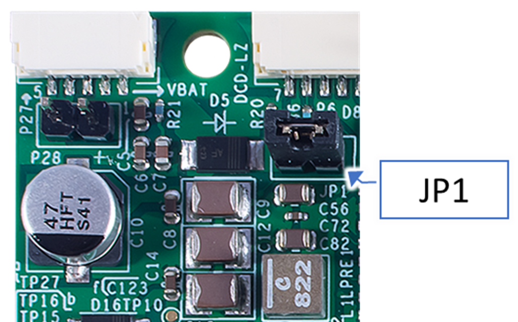
3.4 Board Power Up Sequence – Circumventing the PMIC WDT
The FS26 is the safety system basis chip (SBC) with low-power fit for ASIL D from NXP and includes a safety watchdog timer (WDT).
In sample code, the challenge watchdog functionality has not been implemented. Instead, during startup of the S32K344 the sample application sends a request to the FS26 to disable the watchdog functionality.
To circumvent the FS26 WDT, the chip must be put into debug mode. This is done by removing JP1 and then supplying 12.0V on power input P27 or P28 and then re-inserting the JP1 jumper.
Once this is done, the reset LED D24 should no longer blink, indicating the S32K344 will not reset continuously by the FS26.
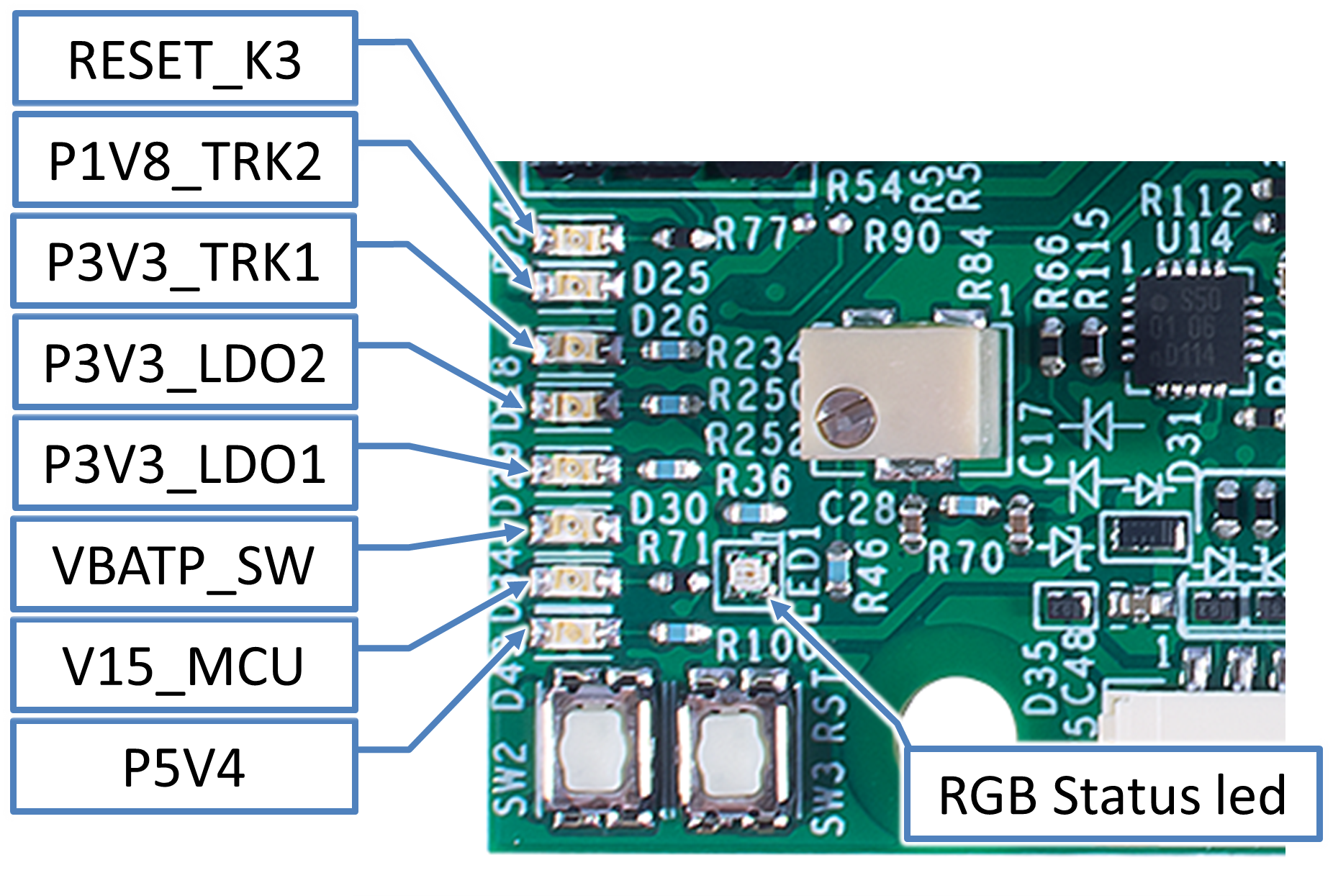
3.5 Board Status LEDs
| Dxx | LED Name | Normal State | Description |
D24 |
RESET_K3 | Off | Indicates if the S32K344 is in reset |
D25 |
P1V8_TRK2 | On | Indicates FS26 SBC 1V8_TRK2 status |
D26 |
P3V3_TRK1 | On | Indicates FS26 SBC 3V3_TRK1 status |
D28 |
P3V3_LDO2 | On | Indicates FS26 SBC 3V3_LDO2 status |
D29 |
P3V3_LDO1 | On | Indicates FS26 SBC 3V3_LDO1 status |
D30 |
VBATP_SW | On | Indicates VBAT status |
D34 |
V15_MCU | On | Indicates FS26 SBC V15 status |
D43 |
P5V4 | On | Indicates FS26 SBC P5V4 status |
LED1 |
RGB Status led | Green | Controlled by the software, green indicates normal operation, blue indicates initialization, red indicates that an error has occurred. |
4. Run the Software
4.1 Import the Project
To import the included Project.zip, open File → Import → General → Project from Folder or Archive and then select the Project.zip archive.
4.2 S32 Pin Tool
Once the project has been imported, right click on “MR_CANHUBK3_IEEE1722” in the projects explorer and select S32 Configuration Tools → Open Pins.
The S32 Pin tool perspective view will appear and in the menu click the button “Update Code” and select “OK”. The driver configuration files will be generated.
4.3 Build Project
Go back to the Project Explorer right click on “MR_CANHUBK3_IEEE1722” and select “Build Project”. Now you can flash the “MR_CANHUBK3_IEEE1722.elf” using your programmer.
For more information regarding S32 Design Studio, S32 Configuration Tools and debugging please refer to the to the “Getting Started with S32K3 and S32DS” guide.
4.4 Simulate CAN Messages
You can also simulate CAN messages by pressing SW1 or SW2.
Connect CAN0 (P12) back to CAN1 (P14) to create a bus using included cable. Also connect the CAN-Term board to P13 to terminate the bus.
When pressing either SW1 or SW2, both LEDs D7 and D22 turn on briefly indicating the presence of a CAN packet.
SW1 will send a CAN message to CAN0 and SW2 will send a CAN message to CAN1.