Getting Started with MPC5777C-DEVB2
Last Modified:
Apr 10, 2024Supports
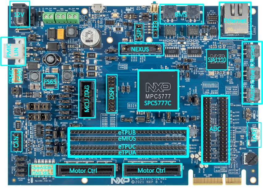
MPC5777C BMS and Engine Control Development Board 2
Contents of this document
-
Out of the Box
-
Get Software
-
Running an Example Application
Sign in to save your progress. Don't have an account? Create one.
Purchase your MPC5777C BMS and Engine Control Development Board 2

2. Get Software
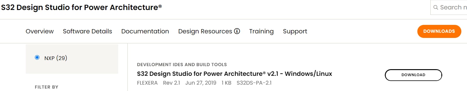
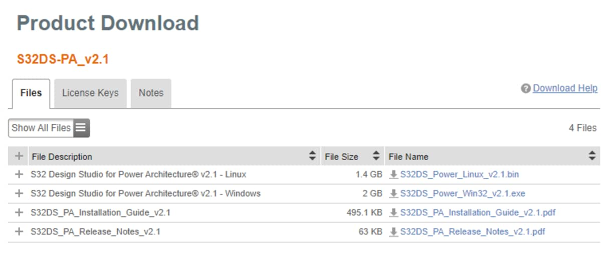
2.1 Download S32 Design Studio
- Download S32 Design Studio for Power Architecture from S32 Design Studio IDE for Power Architecture. Follow the installation guide to complete the installation
- A serial console will be used to read the output and send command to the board while running the example in this guide. Download and install the latest Termite serial console client from Termite: a simple RS232 terminal
- Download and install the USB Multilink Resources Install driver from PEmicro Documentation and Downloads for the USB Multilink Universal FX debug probe. This is required for the debug probe to communicate to the PC via USB
- Download and install the VCP drivers from FTDI Chip Drivers . This is required for the MPC5777C-DEVB2 board to talk to the PC via USB
3. Running an Example Application
3.1 Launch S32 Design Studio
- Launch S32 Design Studio for Power Architecture. Click File → New → S32DS Project from Example
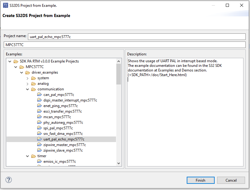
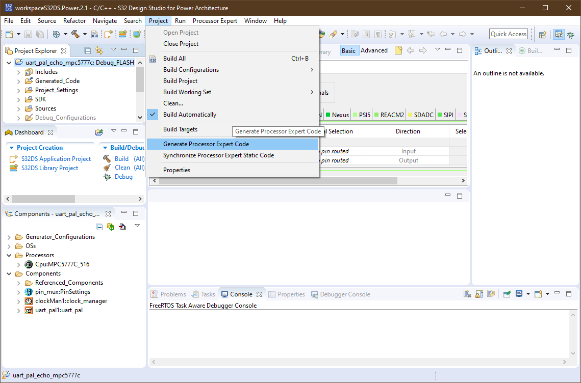
- In the drop down menu, select the
uart_pal_echo_mpc5777cand click Finish. It is easier to find the project by typing mpc5777 in the search field to filter out all examples for the device - Once the project has been created, go to Project → Generate Processor Expert Code and wait for it to finish
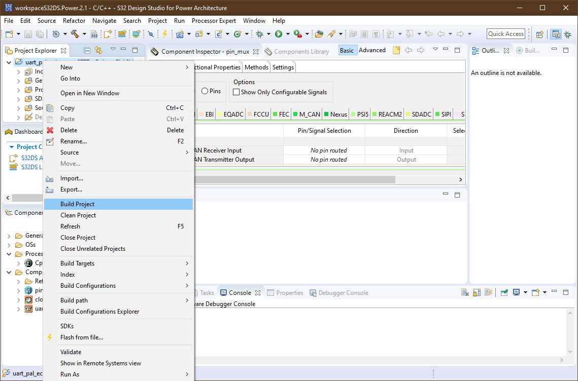
- Build the project by right clicking on the project and selecting Build Project
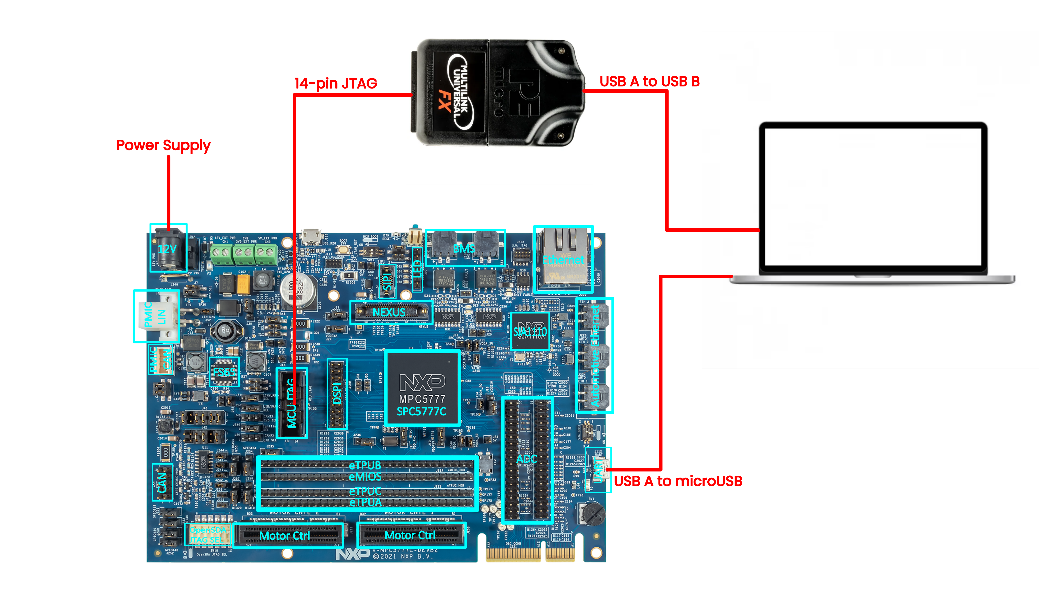
- Make the following connections to the MPC5777C-DEVB2. Connect the 12 V adapter to
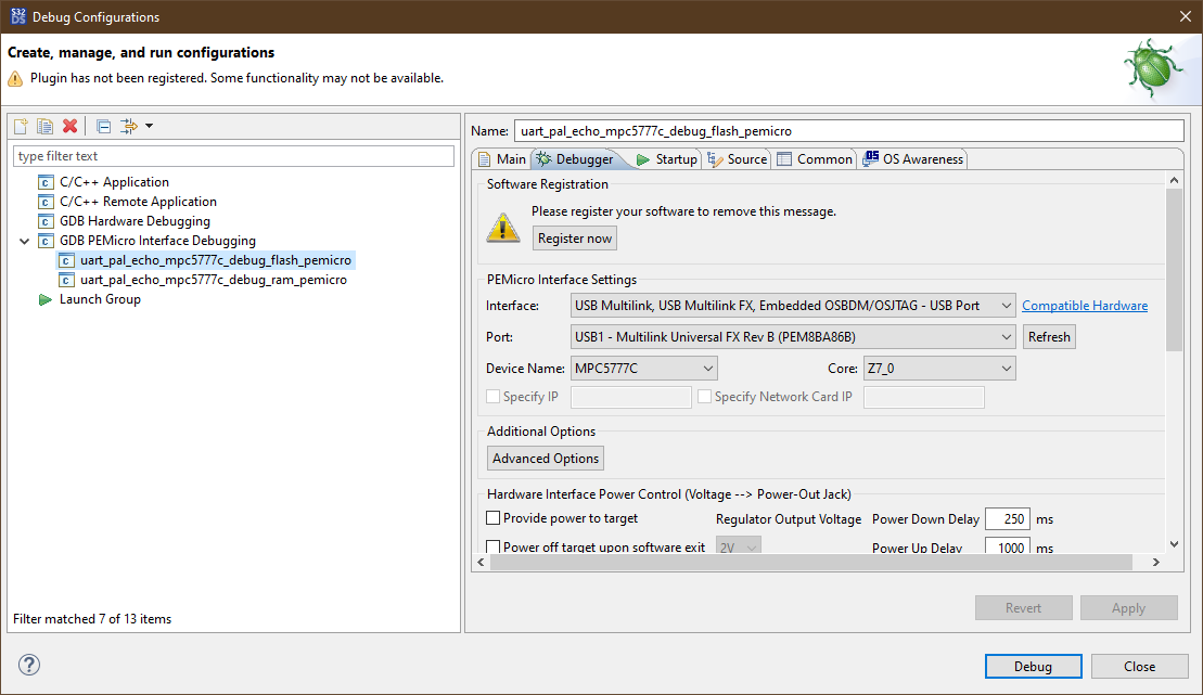
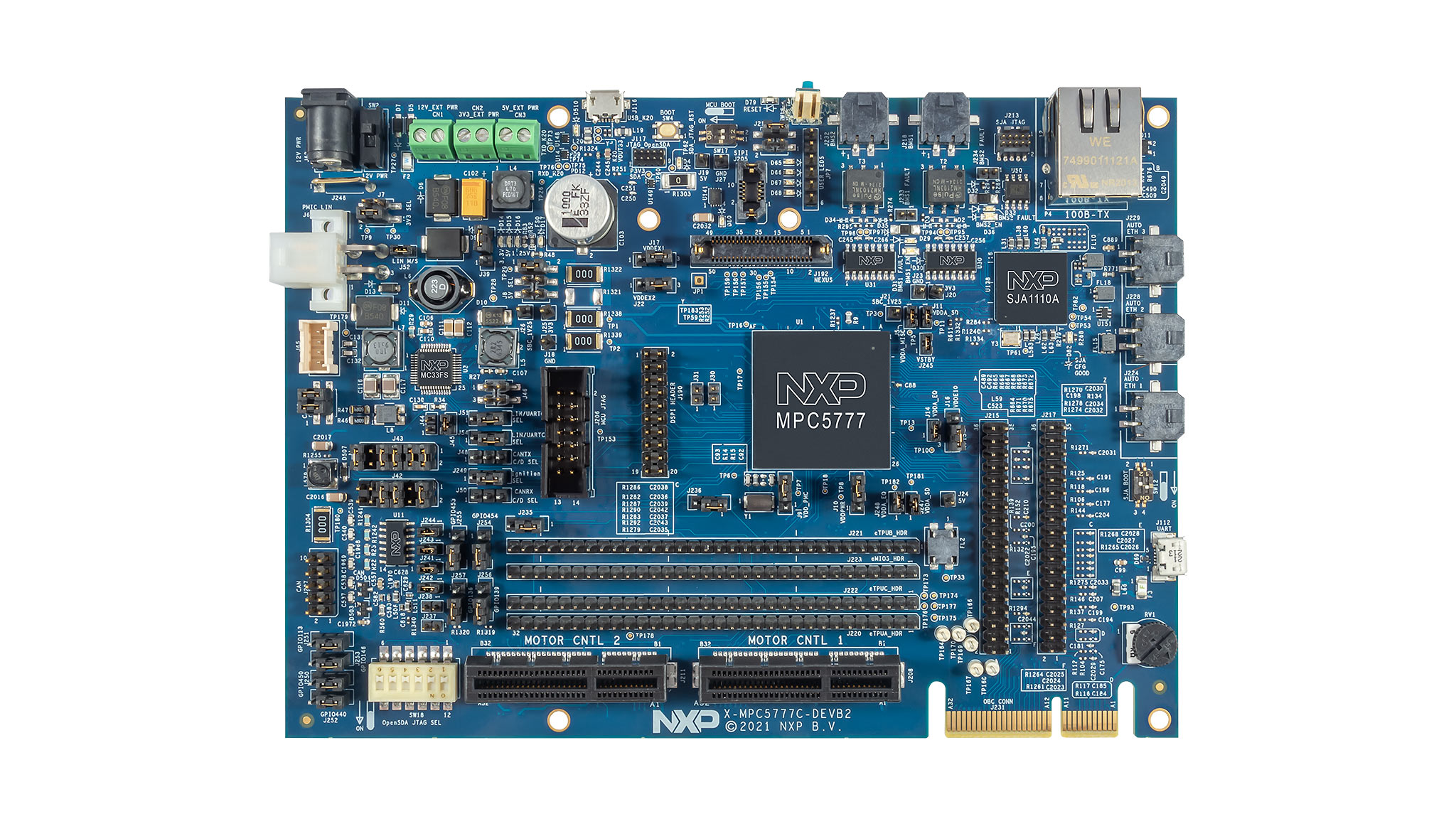
J62. Connect the USB cable from the PC toJ112UART. Connect the Multilink Universal FX debug probe JTAG cable toJ206MCU JTAG. Then connect the USB cable from the PC to the debug probe - Click Run → Debug Configurations and select the compiled project. Verify the connection of the debug probe by checking the port under the Debugger tab. If the connection is successful, the device will show in the Port
- Once verified, turn on the MPC5777C-DEVB2 by toggling the
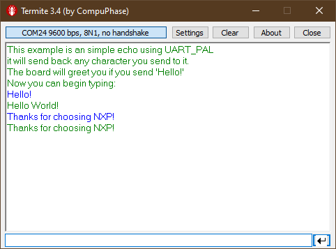
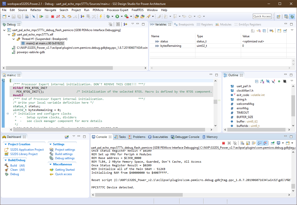
SW2. Click Debug to load the application to the flash on the DEVB2 - Open Termite and modify the serial port settings as following. The COM port number may differ from PC to PC
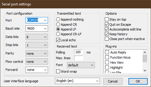
- Reset the DEVB2 by pushing
SW16once. The following message should appear on the Termite serial console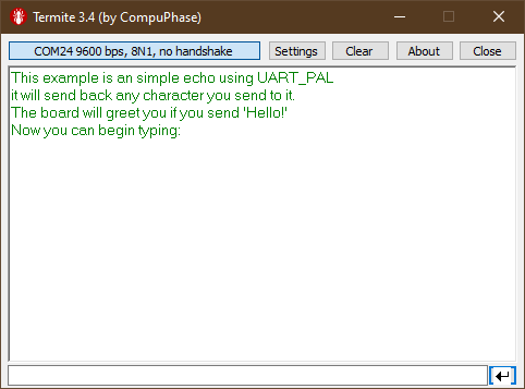
- Verify the program by sending the testing text