Getting Started with i.MX RT1180 Evaluation Kit
Contents of this document
-
Plug it In
-
Get Software
-
Build, Run
-
Create
-
MCUXpresso Developer Experience
Sign in to save your progress. Don't have an account? Create one.
Purchase your i.MX RT1180 Evaluation Kit
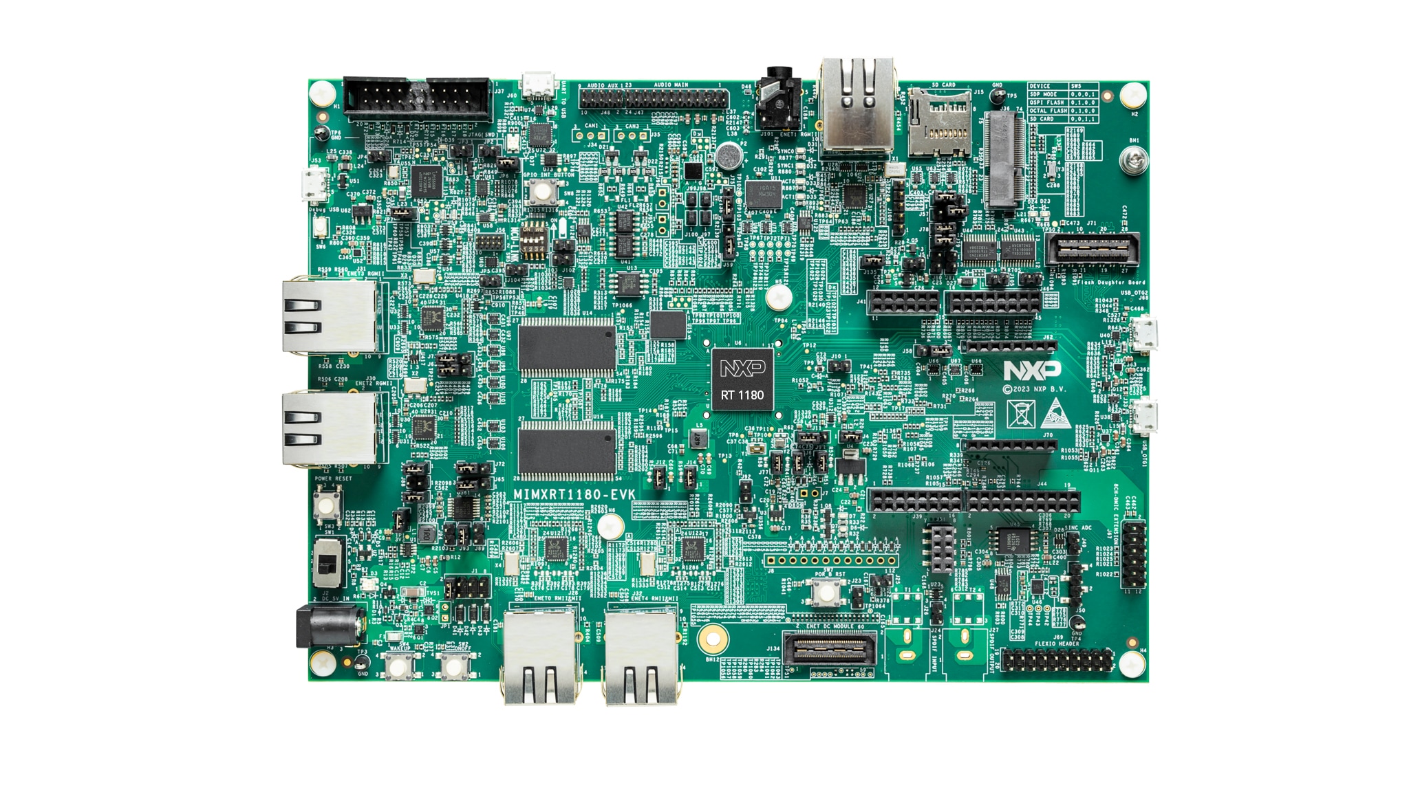
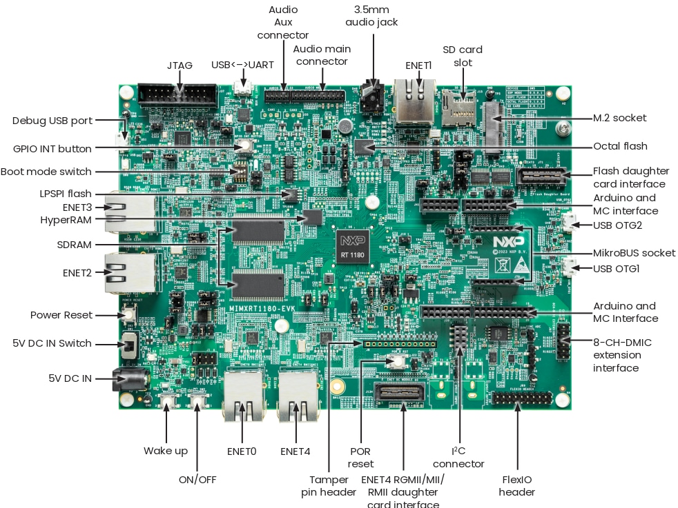
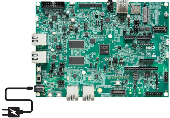
1. Plug it In
Let's take your MIMXRT1180-EVK board for a test drive! You have the choice of watching the sequence in a short video or following the detailed actions listed below.
2. Get Software
2.1 Install Your Toolchain
NXP offers a complimentary toolchain called MCUXpresso IDE. Please download MCUXpresso v11.8.1 or above.
Learn how to install VS Code for your host PC with the following tutorial.
Want to use a different toolchain?
If you need help choosing, explore the MCUXpresso Suite of Software and Tools.
The MCUXpresso SDK includes support for other tools such as IAR , KEIL and command-line GCC .
2.2 Jump Start Your Design with the MCUXpresso SDK
The MCUXpresso SDK is complimentary and includes full source code under a permissive open-source license for all hardware abstraction and peripheral driver software. You may install the MCUXpresso SDK directly form the MCUXpresso SDK website at mcuxpresso.nxp.com. Click on the button below to open this board's SDK builder.

2.3 MCUXpresso Config Tools
The MCUXpresso Config Tool is an integrated suite of configuration tools that guides users in creating new MCUXpresso SDK projects, and also provides pin and clock tools to generate initialization C code for custom board support, it is fully integrated as a part of MCUXpresso IDE and also as a separate tool if using a different IDE.
Click the Get MCUXpresso Config Tools below to get the Config Tools installer.
 Get MCUXPresso Config Tools
2.4 Programming and Provisioning Tools
NXP provides MCUXpresso Secure Provisioning (SEC) for trial run and mass production use. It supports secure programming and device provisioning on NXP's microcontrollers at the production stage. The MCUXpresso Secure Provisioning (SEC) Tool is a GUI-based application provided to simplify generation and provisioning of bootable executables on NXP MCU devices. The Secure Provisioning SDK (SPSDK) is an open-source development kit with its source code released on Github and PyPI. This command-line tool is useful when interfacing with a custom or partner programming tool.

3. Build, Run
If one or more of the demo applications or driver examples sounds interesting, you're probably wanting to know how you can build and debug yourself. The Getting Started with MCUXpresso SDK guide provides easy, step-by-step instructions on how to configure, build, and debug demos for all toolchains supported by the SDK.
3.1 Build and Flash Application using MCUXpresso IDE
The following steps will guide you through the hello_world demo application using MCUXpresso IDE for the Cortex-M33 application. The MCUXpresso IDE installation and the SDK for the i.MX RT1180-Series can be found at the section Get Software of this Getting Started guide. Both CMSIS-DAP and J-Link debugging interface is supported for MCUX IDE. When using CMSIS-DAP debugging interface, the SW5[1..4] should be put to 0100. When using J-Link debugging interface, the SW5[1..4] should be put to 0001.
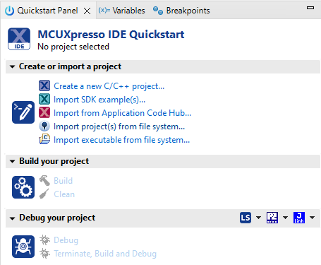
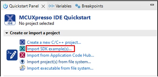
- Find the Quickstart Panel in the lower left-hand corner
- Then click on Import SDK example(s).
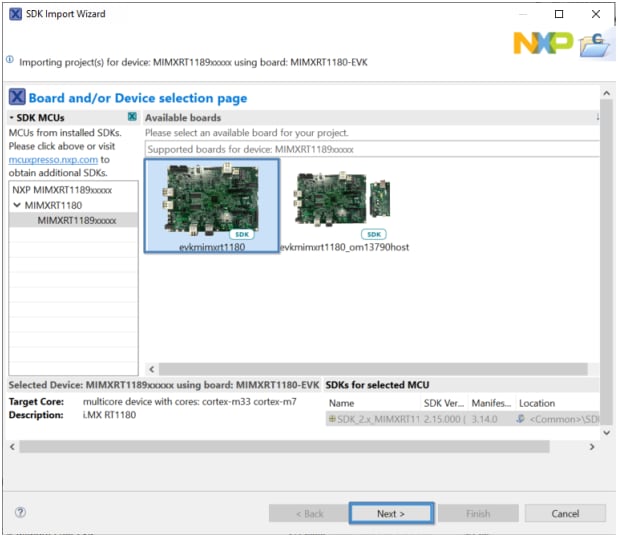
- Click on the evkmimxrt1180 board to select an example that can run on that board, and then click on Next
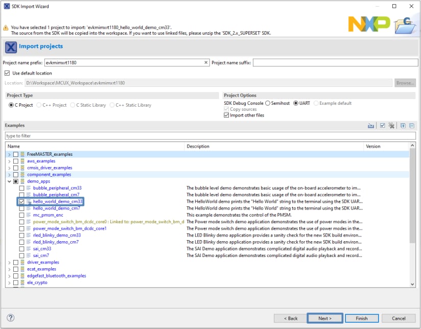
- Use the arrow button to expand the demo_apps category and then click the checkbox next to hello_world to select that project. To use the UART for printing (instead of the default semihosting), select UART as the SDK Debug Console checkbox under the project options. Then, click on Finish
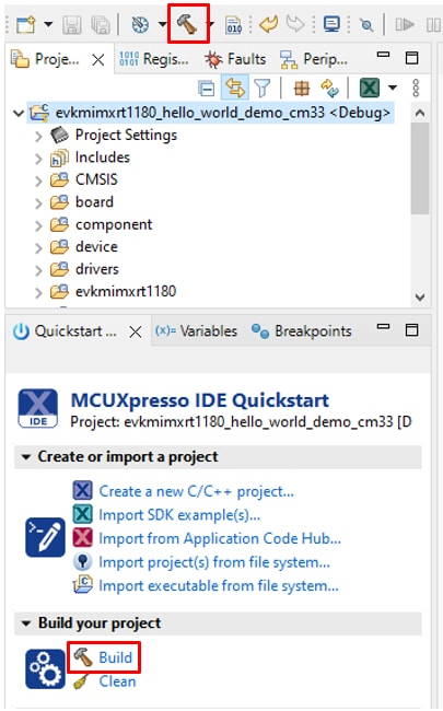
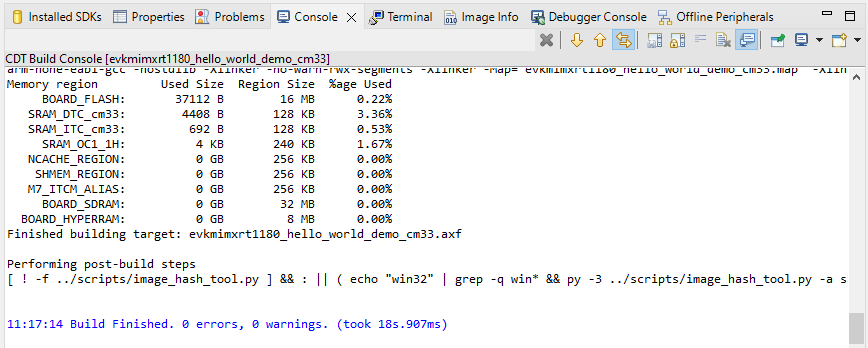
- Select the project and build it by either clicking on the “build icon” in the shortcuts provided above or by clicking “Build” in the Quickstart Panel
- The project should build without presenting any errors or warnings in the console
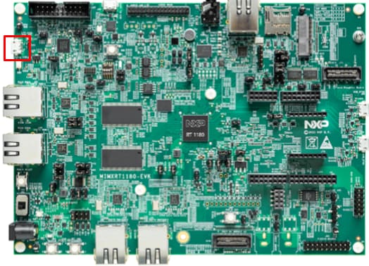
- Connect the board to your computer with the micro USB to J53 'MCU-LINK' port
- Download the application to your board by either clicking on the “debug” icon above or clicking on “Debug” in the Quickstart Panel
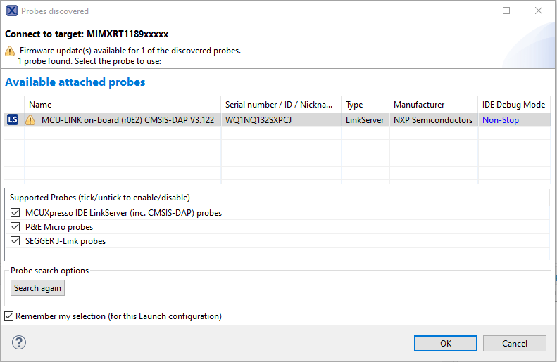
- Select the MCU-Link CMSIS-DAP debug probe
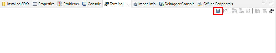
- Open up a serial terminal to be able to see the application's output. Select the “Terminal” window and press the “new terminal” icon
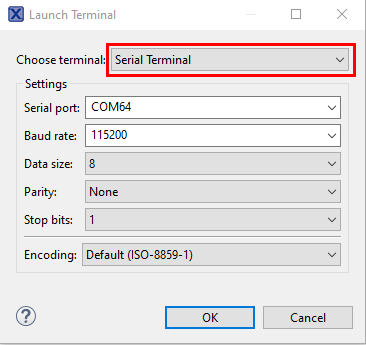
- Choose a “Serial Terminal” and then set the UART settings to 115200 baudrate, 8 bit data size, no parity and 1 stop bit. Press OK
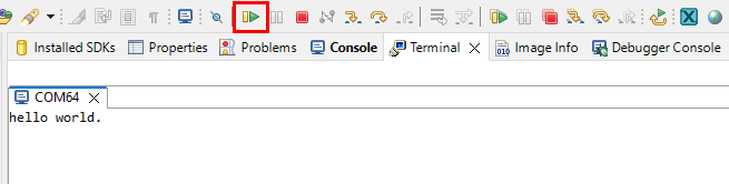
- Run the application by pressing the “run” icon. See the output printed on the terminal
3.2 Build and Flash Application with Alternative Toolchains
MCUXpresso for Visual Studio Code (VS Code) provides an optimized embedded developer experience for code editing and development. Learn how to build and flash an application with VS Code.
Using a different toolchain?
This demo is also available for IAR and KEIL.
4. Create
4.1 Clone an Example Project from MCUXpresso IDE
Refer to section 3.1 about "Import SDK example(s)", the example will be cloned to be a standalone project in MCUXpresso IDE, any changes of the code will not affect the original example files.

4.2 Clone an Example Project using MCUXpresso Config Tool for 3rd Party IDE
The following steps will guide you through the manipulation of the general-purpose outputs. The example sets up systick interrupt to realize the timing delay and turns to shine the LED.
- Open the MCUXpresso Config Tool
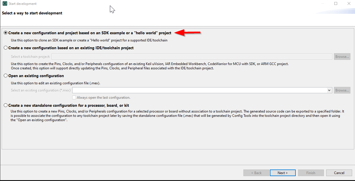
- In the wizard that comes up, select the “Create a new configuration based on an SDK example or hello word project” radio button and click on Next
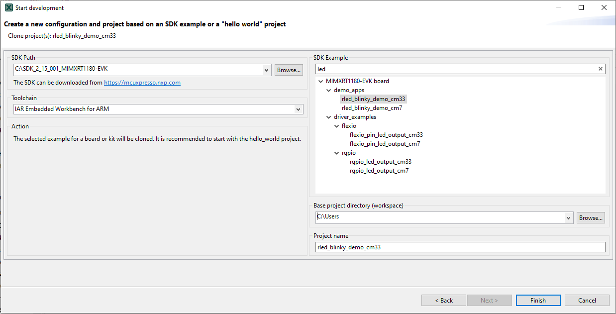
- On the next screen, select the location of the MCUXpresso SDK . The SDK package must be unzipped beforehand. Then select the IDE that is being used. Note that only IDEs that were selected in the online SDK builder when the SDK was built will be available and click on clone select example. Then select the project to clone. For this example, we want to use the gpio led output project. You can filter for this by typing “LED” in the filter box and then selecting the “rled_blinky_demo_cm33” example project. You can then also specify where to clone the project and the name. Then click on Finish
- After cloning go to the directory you selected and open the project for your IDE. Import, compile and run the project as done in previous sections
- You should see the GREEN LED blinky
- Terminate the debug session
4.3 Use MCUXpresso IDE Pins Tools
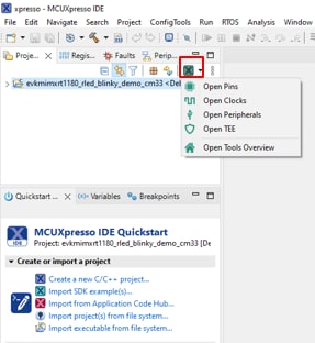
- Open the pins tool by selecting “ConfigTools” on the top right hand of the file explorer window and then select “Open Pins”
- The pins tool should now display the pin configuration for the LED blinky project
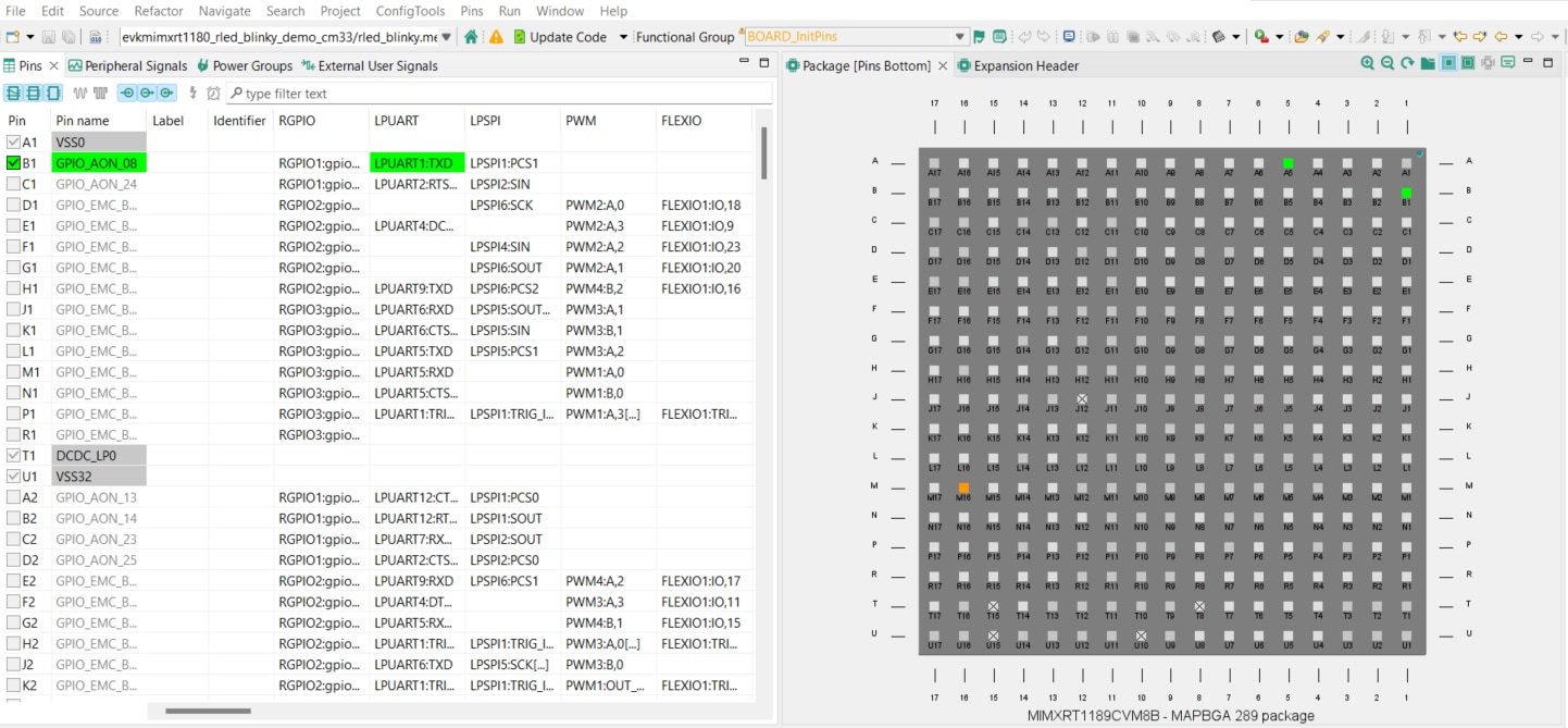
4.4 Use the Pins Tools to Modify the LED Routed Pin
- We'll use MCUXpresso IDE for the rest of the instructions, but the same steps can be done in MCUXpresso Config tools for third party IDEs. In the Pins view deselect “Show dedicated pins” and “Show no routed pins” checkboxes to see only the routed pins. Routed pins have a check in a green box next to the pin name. The functions selected for each routed pin are highlighted in green.
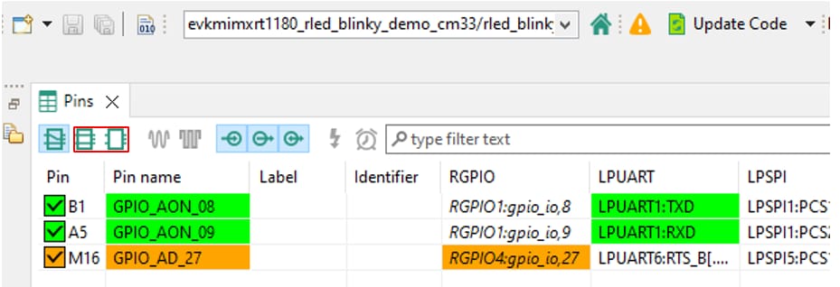
- In the current configuration, GPIO_AD_27 is routed as the output for GREEN LED. Let's add the pin configuration to enable the RED LED.
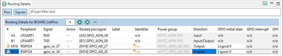
- Select “Show no routed pins” to see the other options. To enable the RED LED, search for GPIO_AD_26 and set it to "RGPIO4:gpio_io,26"
- Next configure the GPIO pin as an output in the “Routing Details” window
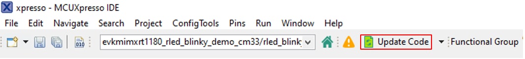
- Now it's time to implement these changes into the project by exporting the new updated pin_mux.c and pin_mux.h files that are generated by the Pins tool. Click on Update Project in the menu bar
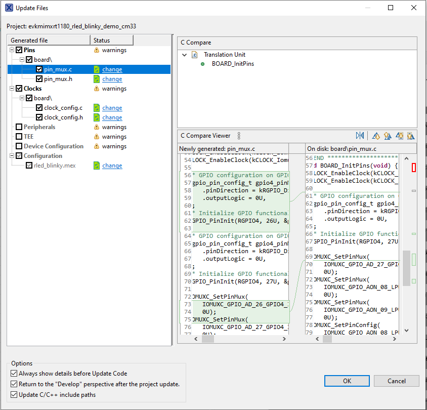
- The screen that pops up will show the files that are changing and you can click on “change” to see the difference between the current file and the new file generated by the Pins tool. Click on “OK” to overwrite the new files into your project.
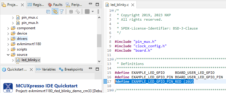
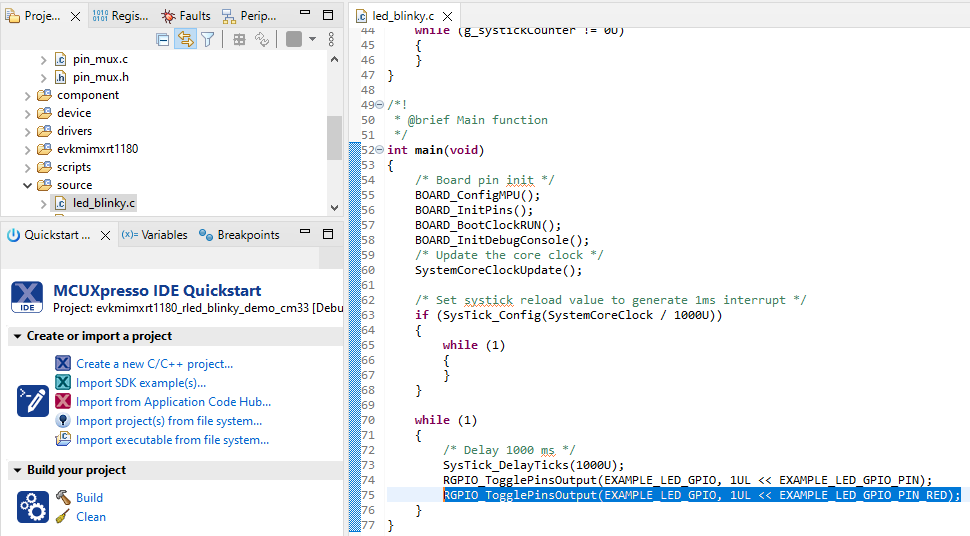
- Let's add some additional code to the example. Open led_blinky.c file and add the new macro for RED LED
- In the main function, add one more RGPIO_TogglePinsOutput calling for RED LED
- Build and download the project as done in the previous section
- Run the application. You should now see the Green and RED LED blinking
- Terminate the debug session
5. MCUXpresso Developer Experience
Check out each of the following sections, to learn about the ecosystem provided for flexible protyping and development. In the video below, we will introduce you to the MIMXRT1180-EVK platform.
5.1 MIMXRT1180-EVK Platform
For quick prototyping platforms, we offer MIMXRT1180-EVK.
MIMXRT1180-EVK Development Boards come with standard form factor and headers, easy access to MCU I/Os, on-board MCU-Link debugger and a USB-C cable. Our full features evaluation kits include extended I/O and interface access, extendable with WiFi and additional MCU-Link features.There are also many compatible Click Board and/or Arduino shields. For those that are supported with an Open CMSIS Pack examples may be available on ACH, but if not many of them are easy to use via serial interface like I2C, SPI and UART, for which we provide drivers with examples in the MCUXpresso SDK.
Boot Options
| Documents and Videos | Application Note SW (if applicable) | Description |
|---|---|---|
| SPSDK and secure boot | ||
| How to utilize trace modules on RT1180 |
Tools and References
MCUXpresso Secure Provisioning Tool A GUI-based application provided to simply the generation and provisioning of bootable executables on NXP devices.
Community Resources for Booting Look for answers to your boot questions or submit new questions in our Community.
External Memory
| Documents and Videos | Application Note SW (if applicable) | Description |
|---|---|---|
| How to use FlexSPI follower |
MCUXpresso SDK Examples
Several examples, demos and drivers are available within the SDK to help you get started. Some common examples for external memory are listed below.
FlexSPI Nor Flash Polling Example
1<SDK_PATH>\boards\evkmimxrt1180\driver_examples\flexspi\nor\polling_transfer 1<SDK_PATH>\boards\evkmimxrt1180\driver examples\flexspi\nor\edma_transfer 1<SDK_PATH>\boards\evkmimxrt1180\driver_examples\flexspi\octal\polling_transfer 1<SDK_PATH>\boards\evkmimxrt1180\driver examples\flexspi\octal\edma_transfer 1<SDK_PATH>\boards\evkmimxrt1180\driver_examples\semc\sdram Design Resources
Support
On this page
- 2.1
Install Your Toolchain
- 2.2
Jump Start Your Design with the MCUXpresso SDK
- 2.3
MCUXpresso Config Tools
- 2.4
Programming and Provisioning Tools
- 3.1
Build and Flash Application using MCUXpresso IDE
- 3.2
Build and Flash Application with Alternative Toolchains