Getting Started with the RDBESS774A1EVB
Contents of this document
-
Out of the Box
-
Get Hardware
-
Configure Hardware
Sign in to save your progress. Don't have an account? Create one.
Purchase your RDBESS774A1EVB
1. Out of the Box
The NXP analog product development boards provide an easy-to-use platform for evaluating NXP products. The boards support a range of analog, mixed-signal and power solutions. They incorporate monolithic integrated circuits and system-in-package devices that use proven high-volume technology. NXP products offer longer battery life, a smaller form factor, reduced component counts, lower cost, and improved performance in powering state-of-the-art systems.
This page will guide you through the process of setting up and using the RDBESS774A1EVB evaluation board.
1.1 Kit Contents
The RDBESS774A1EVB contents include:
- Assembled and tested evaluation board/module in antistatic bag
- One cell terminal cable
- One transformer physical layer (TPL) cable
1.2 Additional Hardware
To use this kit, the following hardware is required:
- A 4-cell to 18-cell battery pack or a battery-pack emulator, such as BATT-18CEMULATOR
-
A TPL communication system. If a user-specific system is not available, the evaluation setup or the 1500 V high-voltage battery energy storage system (HVBESS) reference design can be used.
- The 1500 V HVBESS reference design consists of the HVBESS battery management unit (RD- BESSK358BMU) and the 1500 V HVBESS battery junction box (RDBESS772BJBEVB). For the 1500 V HVBESS reference design, a graphical user interface (GUI) is available.
- The evaluation setup consists of the FRDM665SPIEVB (EVB for MC33665A) with the S32K3X4EVB-T172 (S32K3X4 EVB)
- For the evaluation setup, EvalGUI 7 is available.
2. Get Hardware
2.1 Board Features
- Reference design with three MC33774A, showing an optimized bill of materials (BOM) as outlined in the data sheet
- Capacitive isolation for onboard communication
- Based on NXP core layout for MC33774A; core layout is used for NXP internal electromagnetic compatibility (EMC) and hotplug tests
- Four-layer board, all components are assembled only on the top side
- Cell electrostatic discharge (ESD) capacitors package 0805
- 0805 packages used for all signals with a voltage higher than approximately 25 V
- Three 1206 surface mounted device (SMD) resistors per balancing channel for individual cell-voltage balancing
- All eight external thermistor inputs are available
- Onboard high-performance, high-precision absolute pressure sensor
- Placeholder for I²C-bus EEPROM
- Can be used together with the 1500 V HVBESS reference design or the evaluation setup
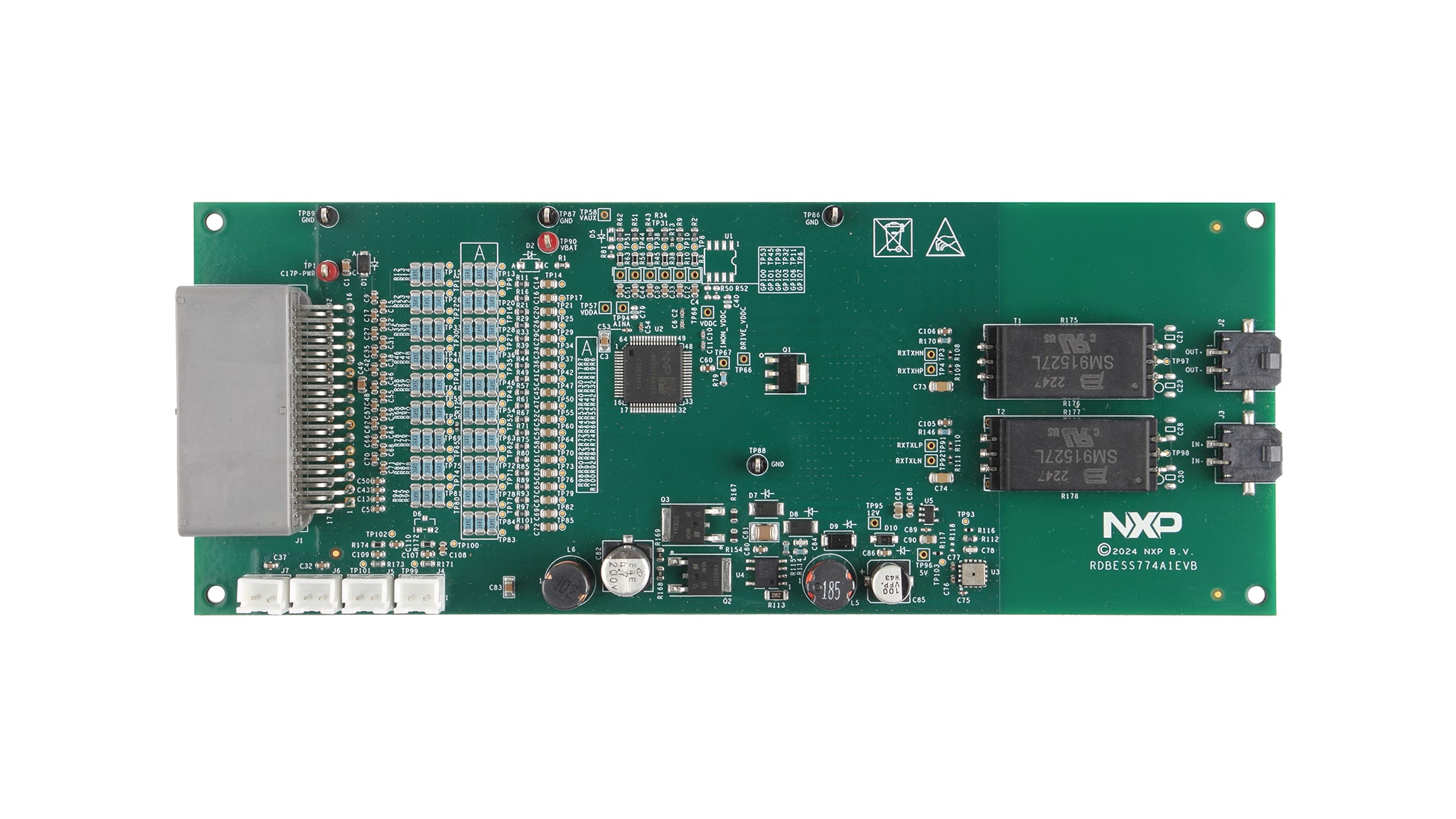
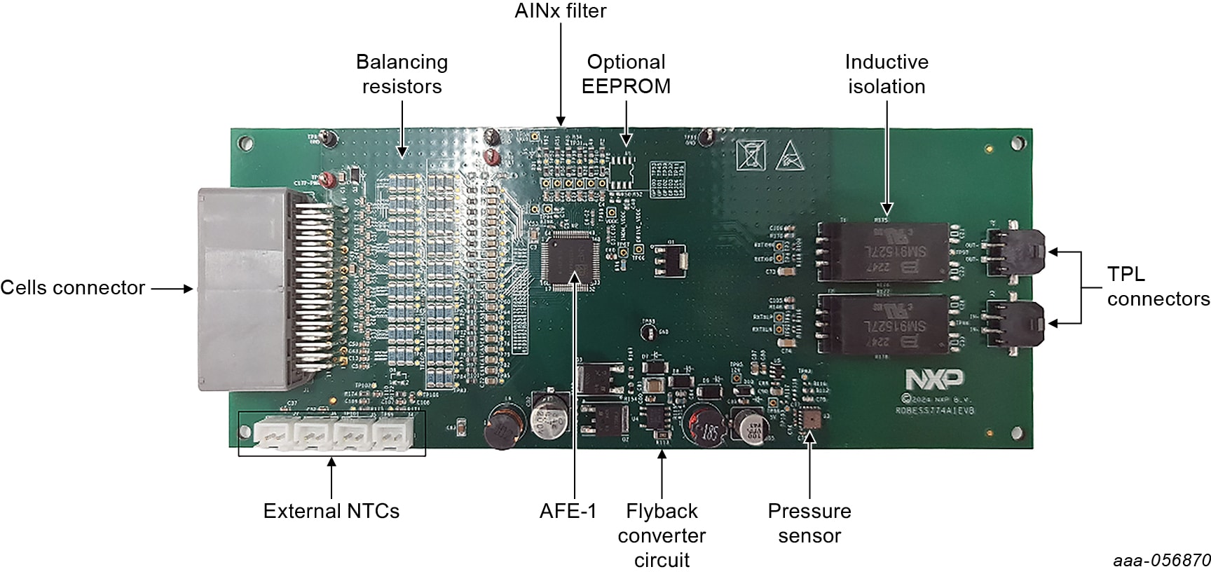
2.2 Board Description
The RDBESS774A1EVB is a hardware evaluation tool supporting the NXP MC33774A device. The RDBESS774A1EVB implements three MC33774A battery cell controller ICs. The MC33774A is a battery-cell controller that monitors up to 18 Li-ion battery cells. It is designed for use in both automotive and industrial applications. The device performs analog-to-digital conversions (ADC) on the differential cell voltages. It is also capable of temperature measurements and can forward communication via an I²C-bus to other devices. The RDBESS774A1EVB is an ideal platform for rapid prototyping of MC33774A-based applications that involve voltage and temperature sensing.
The RDBESS774A1EVB measures the pressure of the battery module using the onboard FXPS7250A4ST1 pressure sensor. The RDBESS774A1EVB converts the battery module voltage to 12 V using the TEA1721AT/ N1,118 flyback controller, then converts the 12 V to 5 V to supply the pressure sensor.
The RDBESS774A1EVB uses inductive isolation for offboard communication. The galvanic isolation for onboard communication is established via capacitors.
The RDBESS774A1EVB is also used as part of the 1500 V HVBESS reference design consisting of the HVBESS battery management unit (BMU) and the 1500 V HVBESS battery junction box (BJB).
With the RDBESS774A1EVB, the user can explore all functions of the MC33774A battery-cell controller.
Configure Hardware
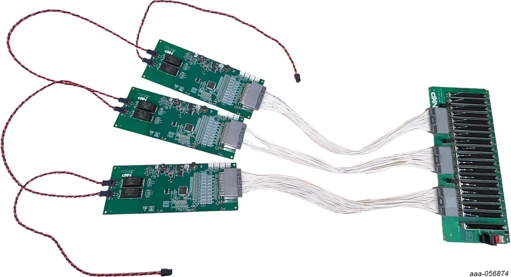
3.1 Battery Emulator Connection
A minimum of four cells and a maximum of 18 cells can be monitored by one MC33774A. NXP provides an 18- cell battery emulator board, BATT-18EMULATOR. This board provides an intuitive way to change the voltage across any of the 18 cells of an emulated battery pack. The board RDBESS774A1EVB can be connected to an 18-cell battery emulator board using the connectors J2 and J3, with the provided supply cable. See Figure 2.

Design Resources
Additional References
In addition to the HVBMS Centralized Cell Monitoring Unit Using ETPL with MC33774ATA page, you may also want to visit: