Getting Started with the RD33772C14VEVM Reference Design
Contents of this document
-
Out of the Box
-
Get Hardware
-
Configure Hardware
Sign in to save your progress. Don't have an account? Create one.

Purchase your RD33772C14VEVM
1. Out of the Box
The NXP analog product development boards provide an easy-to-use platform for evaluating NXP products. The boards support a range of analog, mixed-signal and power solutions. They incorporate monolithic integrated circuits and system-in-package devices that use proven high-volume technology. NXP products offer longer battery life, a smaller form factor, reduced component counts, lower cost, and improved performance in powering state-of-the-art systems.
This page will guide you through the process of setting up and using the RD33772C14VEVM board.
1.1 Kit Content and Packing List
The RD33772C14VEVM kit contents include:
- Assembled and tested evaluation board/module in anti-static bag
- Several cables
- Quick start guide
1.2 Additional Hardware
In addition to the kit contents, the following hardware is necessary or beneficial when working with this kit:
- Low-voltage power supply 5.0 V to 14 V with current limit set initially to 1.5 A
- Current load, 0 A to 500 A
- Controller area network (CAN) card and cable
- Multilink FX debugger cable
2. Get Hardware
2.1 Board Features
- Power supply input from 9.0 V to 18 V
- Up to 10 channels temperature sensing
- Up to 4 channels pack voltage measurement
- Redundant current measurement
- External positive temperature coefficient (PTC) for self-heating function of lithium-ion battery
- Hardware short-circuit protection and software (SW) overcurrent protection
- 1 channel CAN and 1 channel local interconnect network (LIN) communication with vehicle control unit (VCU)
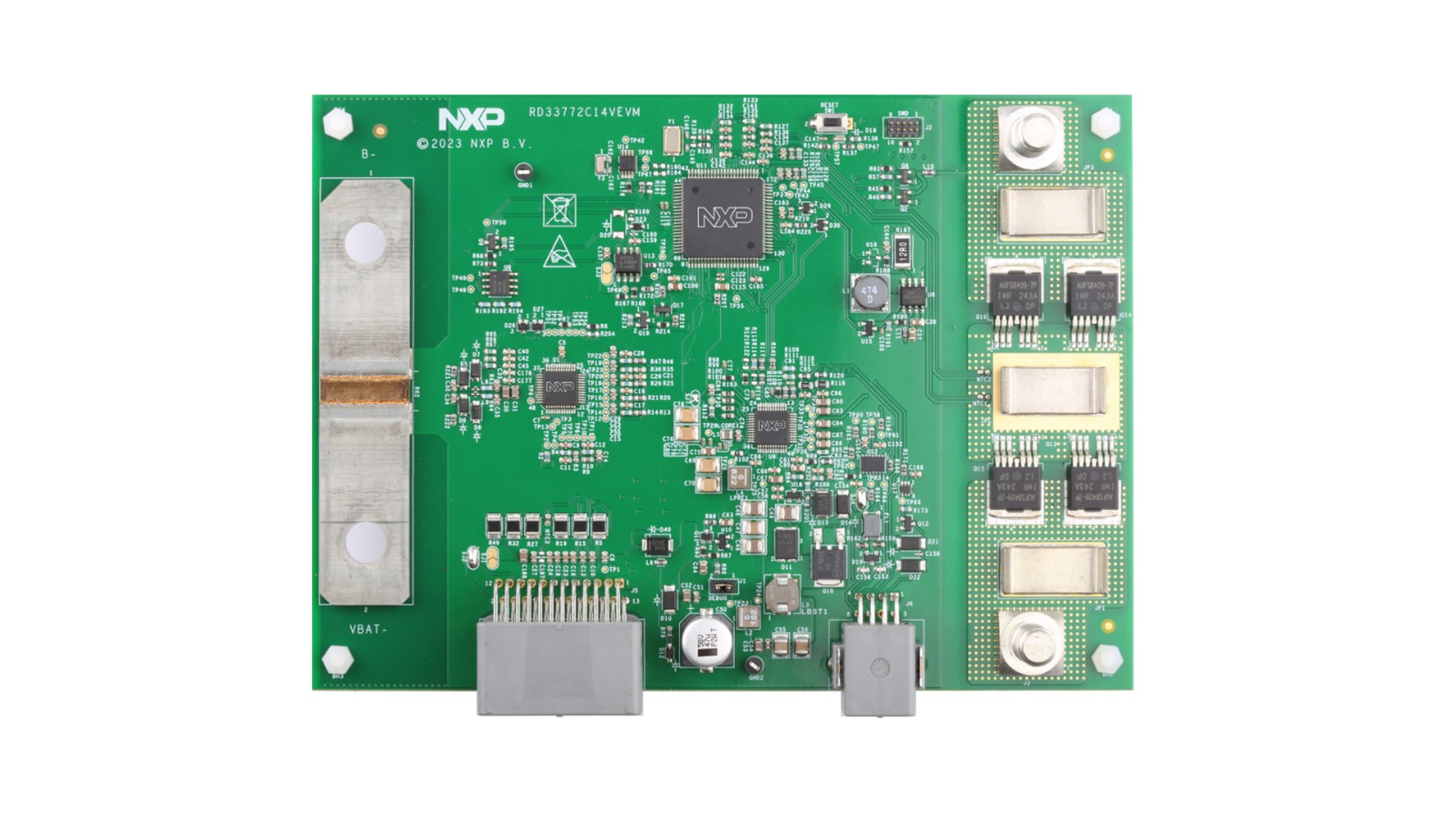
2.2 Board Description
The RD33772C14VEVM is a hardware tool for evaluation and development and is ideal for rapid prototyping of a 14 V BMS. This board can be used to evaluate the features of the MC33772C device.
2.3 Board Components
This reference design features the following NXP products:
| Device | Description |
|---|---|
| MC33772C | 6-channel Li-ion battery cell controller IC |
| S32K344 | AEC-Q100 qualified 32-bit Arm Cortex‑M7‑based MCUs targeted for general purpose automotive and high‑reliability industrial applications |
| FS26 | Safety system basis chip (SBC) with low power fit for ASIL D |
| TJA1021 | LIN2.1/Society of automotive engineers (SAE) J2602 transceiver |
| TJA1145 | High speed CAN transceiver |
3. Configure Hardware
3.1 Configure the Hardware
The RD33772C14VEVM is used in a standalone configuration. There is no connector to add an expansion board. All required cables are included in the kit.
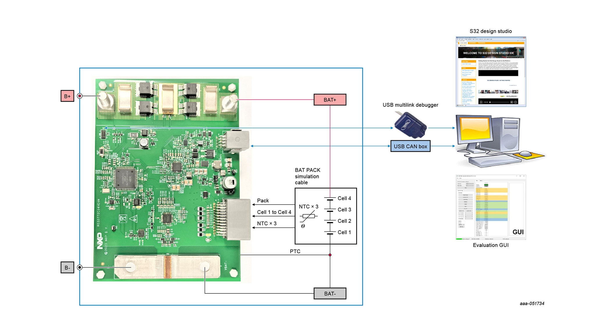
- Connect an external 12 V DC power source supply B+ and B− to power on the board
- Connect the low-voltage connector to
J6, the CAN/local interconnect network (LIN) wire communicates with PC with external CAN/LIN tool - Connect battery simulation cable to
J5and source from 12 V DC - Connect the debug tool to
J2for software purpose