Getting Started with the RD33772BJBEVM
Contents of this document
-
Get Started
-
Get Hardware
-
Configure Hardware
-
Install Software
Sign in to save your progress. Don't have an account? Create one.

Purchase your High Voltage Battery Junction Box Reference Design
1. Get Started
The NXP analog product development boards provide an easy-to-use platform for evaluating NXP products. The boards support a range of analog, mixed-signal, and power solutions. They incorporate monolithic integrated circuits and system-in-package devices that use proven high-volume technology. NXP products offer longer battery life, a smaller form factor, reduced component counts, lower cost, and improved performance in powering state-of-the-art systems.
This page will guide you through the process of setting up and using the RD33772BJBEVM board.
1.1 Kit Contents/Packing List
The RD33772BJBEVM contents include:
- Assembled and tested RD33772BJBEVM board in an anti-static bag
- Cable Assy, 22 AWG (red) L 200 mm, 10-pin W/ crimp terminals
- Cable Assy, 22 AWG (red) L 200 mm, 12-pin W/ crimp terminals
- Cable Assy, 22 AWG (red) L 200 mm, 5-pin W/ crimp terminals
- Quick Start Guide
1.2 Additional Hardware
In addition to the kit contents, the following hardware is necessary or beneficial when working with this kit.
- Low voltage power supply 5.0 V to 12 V with current limit set initially to 1.5 A
- High-voltage DC power supply, 0 to 600 V output
- Current load, 0 to 500 A
- CAN card and cable
- Multilink FX
1.3 Windows PC Workstation
This reference design requires a Windows PC workstation. Meeting these minimum specifications should produce great results when working with this reference design.
- Windows 10, 8 or 7 compatible PC with a USB port
1.4 User Manual
Refer to UM11328, RD33772BJBEVM reference design for additional details on the featured components and board configuration.
2. Get to Know the Hardware
2.1 Board Features
- Power supply input from 5.0 V to 12 V
- Up to six channels voltage sensing for high-voltage measurement
- One channel current sensing to measure the charge current and discharge current
- One channel temperature sensing to measure shunt resistor temperature for calibration
- Integrated insulation resistance measurement
- One channel CAN communication to BMU/VCU
2.2 Board Description
The RD33772BJBEVM allows user to connect to power distribution unit (PDU) for voltage sensing, current sensing, temperature sensing and the diagnostic of contactor status.
This reference design enables validation of High-Voltage Battery Junction Box (HV-BJB) in EV.
2.3 Board Components
Overview of the RD33772BJBEVM: High-voltage battery junction box reference design
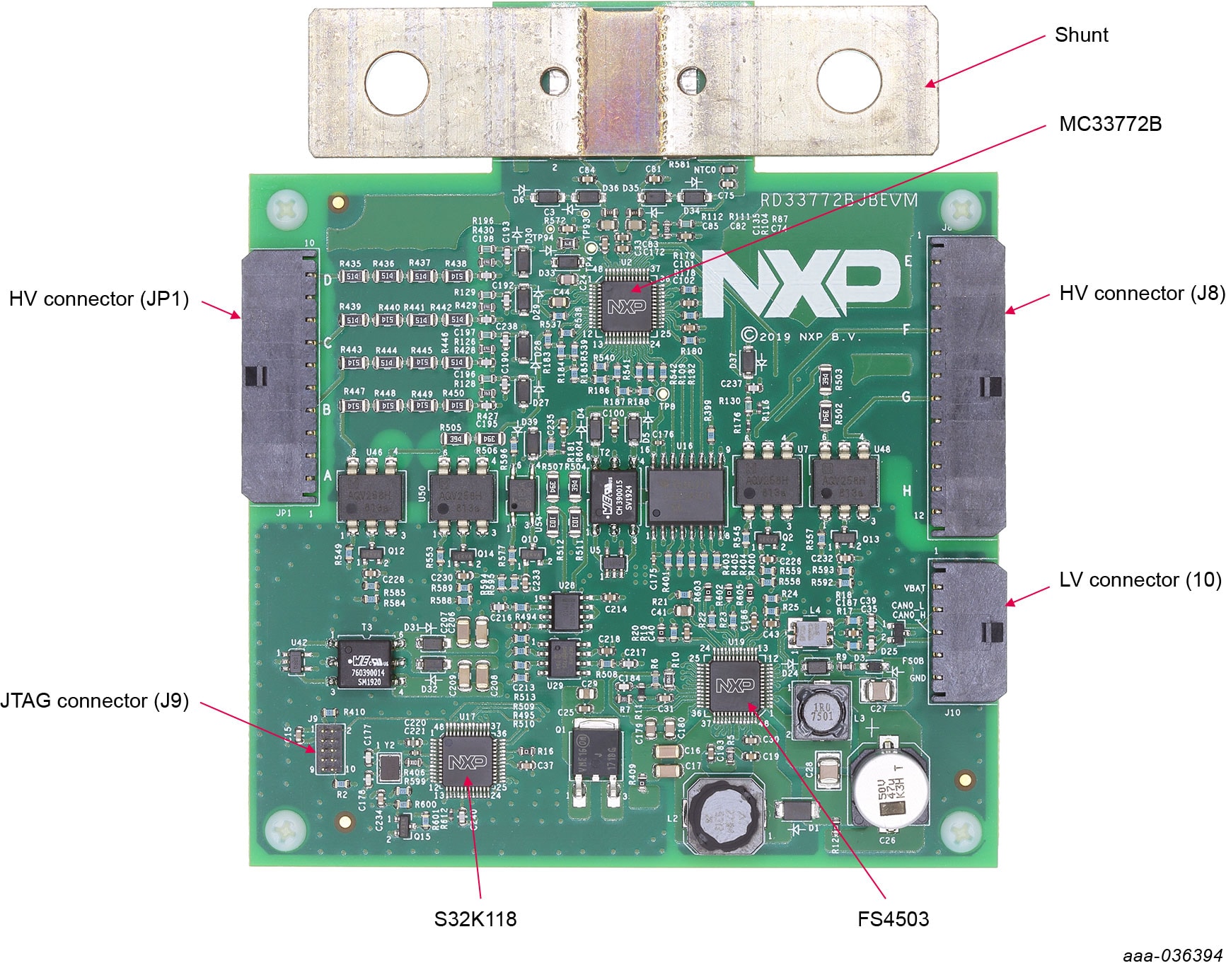
| Name | Description |
|---|---|
| MC33772B | 6-channel li-ion battery cell controller IC |
| FS4503 S32K118 |
Grade 1 and Grade 0 safety power system basis chip with CAN flexible data transceiver Scalable microcontrollers for automotive general purpose and high-reliability industrial |
| HV connector (JP1) | High-voltage connector |
| HV connector (JP8) | High-voltage connector |
| JTAG connector (JP9) | Joint Test Access Group (JTAG) connector |
| LV connector (JP10) | Low voltage connector |
2.4 Additional Board Support
Refer to UM11328, RD33772BJBEVM reference design for additional details on the featured components.
Configure the Hardware
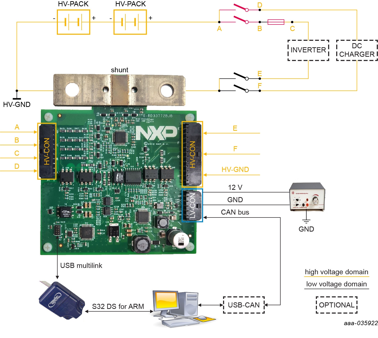
The RD33772BJBEVM is used in a standalone configuration. There are no connectors to add a daughter board. All required cables are included in the kit. To configure the hardware, complete the following procedure:
- Connect power supply cable to
LV_CON, power voltage is 5.0 V to 12 V, current capability is ~300 mA. - Connect the CAN communication cable to
LV_CON. - Connect high voltage sensing cable (A, B, C, D, E and F) to
HV_CON. - Connect PC interface cable to USB connector.
- Connect Debug tool to JTAG connector.
3.1 Additional Board Support
Refer to UM11328, RD33772BJBEVM reference design user manual for additional details on the hardware configuration.
4. Install Software
After configuring the hardware, users have to set up software to perform the examples.
- Install S32 Design Studio IDE for ARM (Version 2018.R1 is recommended).
Note: Registration is required. - Download the desired demo software and extract the project to a local drive.
- Open the installer, then follow the instructions in the setup wizard.
-
In S32 Design Studio for ARM, import the software project.
- From the File menu, select 'Import'.
- Choose 'General > Existing Project into Workspace', and then click 'Next'.
- Click 'Select root directory', and then locate project from step 2. Select 'BJB_S32K118_BCC6_Test project' and click 'Finish'.
- Select 'BJB_S32K118_BCC6_Test' project and Click 'Project > Build Project' to build the project.
-
Debug software project.
- Go to 'Run > Debug Configurations'.
- Double-click 'GDB PEMicro Interface Debugging'.
- Choose 'Main' page, click 'Search Project', then choose 'BJB_S32K118_BCC6_Test.elf' and click 'OK'.
- Choose 'Debugger' page, make sure that USB Multilink is connected correctly, then click 'Select Device' and choose 'S32K118'.
- Click 'Debug'.
Upon completion, the software is download and users are able to debug demo functions. The data or variables can be monitored in the S32K DS tool.
4.1 Additional board support
Refer to UM11328, RD33772BJBEVM reference design user manual for additional software details.
Design Resources
Learn More
Product Summary Page
The product summary page for MC33772B is at 6-Channel Li-Ion Battery Cell Controller IC.
Tool Summary Page
The tool summary page for RD33772BJBEVM reference design is at High Voltage Battery Junction Box Reference Design.
The page provides overview information, technical and functional specifications, ordering information, documentation, and software. The Getting Started provides quick-reference information applicable to using the RD33772BJBEVM reference design, including the downloadable assets.
References
In addition to our MC33772B: 6-Channel Li-ion Battery Cell Controller page, you may also want to visit:
Product pages:
Tool pages:
Application pages:
Hardware pages:
Software pages: