Getting Started with the NXP EdgeReady MCU-Based Solution for 3D Face Recognition
Contents of this document
-
Plug It In
-
Get Software
-
Build, Run
Sign in to save your progress. Don't have an account? Create one.

Purchase your NXP EdgeReady MCU-Based Solution for 3D Face Recognition
1. Plug It In
Welcome to the SLN-VIZN3D-IOT Getting Started Guide! This guide will walk you through the process of getting up and running with your SLN-VIZN3D-IOT. This guide will discuss everything from unboxing your kit, to downloading, modifying and debugging the firmware source code for your kit.
Before we begin, make sure to check the box your kit came in for any marks or other damages, and should you find anything, be sure to report it to your local NXP representative.
1.1 Unbox
The box your kit arrives in should contain a few different things including:
- A Quick Start Card
- USB-A → USB-C cable (x1)
- Four standoff screws
- IR camera module for future updates
- Fully assembled SLN-VIZN3D-IOT kit
It’s worth noting that the box also contains an additional IR camera sensor. This IR camera sensor is for users interested in evaluating only the 2D liveness detection and anti-spoofing capabilities of the kit, so attaching this additional sensor is not necessary for any of the steps in the following sections.
1.2 Power On
Before we begin, make sure to remove the protective film on both the 3D camera and the RGB camera (see below). This protective film is used to protect the lens of each camera during transport. Failing to remove these may cause the the depth and image capture to not work correctly.

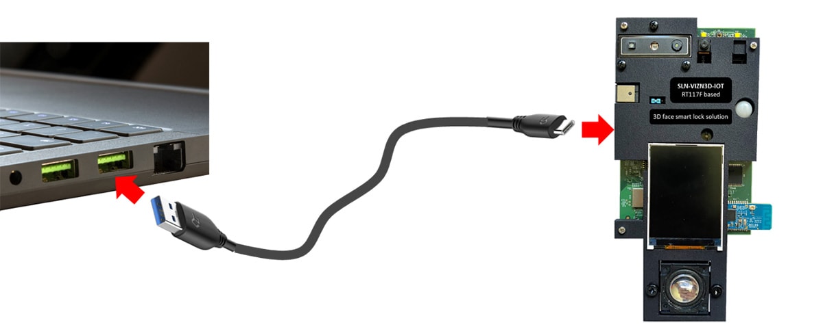
To get started, take the provided USB-C cable and plug the USB-A end into your laptop/PC and the USB-C end into your kit’s USB-C port.

The kit’s USB connector supplies power to the board and supports data transfer capabilities for Mass Storage Device (MSD) programming and virtual serial port communication.
Once the application is ready, your computer will detect a new USB COM device and automatically install the required drivers. A message will confirm when the installation is completed.
After powering on, the onboard TFT screen will stream video directly from the RGB camera alongside a GUI overlay providing information such as:
- Locked/Unlocked Status (whether a face is currently recognized)
- Current App Type (Smart Lock/Access)
- ON/OFF status of Wi-Fi and BLE
- Number of registered users

At this point, the kit is fully operational.
1.3 Local Registration
One of the staple features of the SLN-VIZN3D-IOT is the ability to “register” and recognize faces without any cloud connectivity required whatsoever. By registering a face, the SLN-VIZN3D-IOT can then recognize that face again in the future.
Out of the box, registration can be done locally onboard the kit itself, or remotely using an Android™ smart device.
This section will discuss local registration while the following section will focus on remote registration.

For the purposes of this tutorial, we will focus on registration using the onboard buttons, but for more information regarding registration via shell commands, be sure to check out the SLN-VIZN3D-IOT User Guide.
To begin registering a face, simply press and release the
SW3 push button on the back of the kit.

After releasing the button, the onscreen GUI will change in appearance similar to that shown below, and a corresponding “Starting Registration” audio prompt will be played.

As you can see from the picture above, while registration is taking place, the GUI displays:
- A “Registration” message
- Face alignment guidelines
- A countdown timer bar
The guidelines are used to assist with properly aligning your face during registration, while the countdown timer bar shows how much longer until the registration process will timeout and fail.

As an additional measure to help with registering your face, the kit will even issue a warning audio prompt if too much of the side of your face is visible during the registration process, saying “Look at Camera” until your face is properly pointed towards the camera.
Should your face fail to register, simply press the SW3 button
again to retry.
Once your face is successfully registered, the kit will display a "Registration Successful" message and a unique identifier will be assigned to your face. The number of registered users is automatically updated as well.

After registration has completed, the onscreen GUI will revert back to its original state.

As long as your face remains in the kit’s local database, your face will automatically be recognized by the kit any time it is in view of the camera. An onscreen "Recognition Successful" message and corresponding audio prompt will be played whenever a face is recognized.

Any subsequent attempts to reregister your face while it’s already in the system will produce a "User Already Exists" message and the registration process will fail, in order to prevent duplicate face registrations.

1.4 Remote Registration
While it’s often convenient to register faces locally, there are many use-cases that require the ability to register remotely. For example, imagine a scenario where a hotel registers guests’ faces at a lobby kiosk before sending that face data to the guest’s room so that they can unlock their hotel room door using their face. In use-cases like these, the ability to register remotely is not only convenient; it’s required.
Remote registration on the SLN-VIZN3D-IOT functions similarly to the local registration flow we performed in the previous section, but instead of registering the face on the kit itself, the registration will be done remotely on an Android smartphone or tablet and then transferred to the kit’s local face database wirelessly.

Before we begin, it is important to note that remote registration requires the use of an Android device running Android 8 or higher. If you don’t have an Android device available, feel free to skip this step and jump to the next video.
Before we can perform remote registration, we must first download and install the Smart Lock Manager App on our Android smart device.
To download the Smart Lock Manager app, go to the product page for the SLN-VIZN3D-IOT on the NXP website and navigate to Tools and Software at the bottom of the page:

Install the app by going to the Files App, clicking on Downloads, and selecting the smart_lock_manager.apk file. Tapping on the APK file will ask you to confirm that you want to install the application.

If this is your first time installing an APK file from the web, you may need to “allow app installations from unknown sources.” The process to enable this setting varies from device to device, so check the relevant documentation associated with your device for help.

You may also be required to give additional confirmation if your phone does not recognize the app developer. Once installation has completed, open the application.
The first time the application is opened, you will be prompted to give various permissions required for the app to run correctly. Make sure to approve all of them.

Additionally, verify that Bluetooth is activated on your Android device.

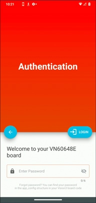
The app’s home screen will display a list of kits within Bluetooth range of your Android device, using a unique identifier for each kit. Select the kit that you want to connect to.

An authentication screen will ask for a password to connect to the board. By
default, this password is 000000.

Once authenticated, the subsequent screen will list the users already registered to the connected kit. From this menu, we can manage the users stored in the kit’s local face database.

Click on the "user_000" listing corresponding to the face we registered locally in the previous step and press the "Delete User" option.

Confirm deletion by clicking "Delete" on the prompt that appears. The "user_000" face will automatically be removed from both the list on your Android device and the local database on your SLN-VIZN3D-IOT.

Now, click the "Add User" button in the lower right-hand corner of the screen.
Align your face with the camera and click the snapshot button at the bottom of the screen once the box around your face turns green.

Assign a username to your face by typing in the text box labeled "Name". Once you are satisfied with the name and picture, click "Register" in the upper right-hand corner of the screen. At this point, the face you just registered will automatically be synced with the connected SLN-VIZN3D-IOT kit.

To confirm successful registration, position your face in front of your SLN-VIZN3D-IOT kit and verify that your face is successfully recognized.
Note: The first time a face remotely registered is recognized, the recognition may take a little longer to compensate for the quality difference between the kit’s camera and the Android device’s camera, used for the (remote) registration.
1.5 Liveness Detection
The Smart Lock application flashed by default on the SLN-VIZN3D-IOT is able to perform “liveness detection” on faces detected by the kit. “Liveness detection” refers to the ability to discern between a real face and a “fake” face (ex. a picture or 3D model of a face). Liveness detection is used to protect against “spoof” attacks in which a malicious user may try to coopt someone’s likeness.

The three main types of spoof attacks that the i.MX RT1170 Smart Lock solution can detect are attacks using pictures on a phone display, printed black and white or color photos, and attacks using 3D models like silicon and rubber masks.

We can test the liveness detection feature by simply presenting a fake face to the camera. A UI message and an audio prompt will confirm when a fake face is detected.

Certain spoof attacks, primarily those using phone displays, may not trigger any feedback whatsoever. This is because no face can be detected by the IR camera.

Of course, spoof attacks in which no face can be detected will not trigger a recognition either, so there is no concern that a spoofing attempt in this scenario might succeed.
1.6 Low-Power Mode
Many battery-based applications require the ability to conserve power during periods of low usage in order to maximize potential battery life. The SLNVIZN3D- IOT was designed with many of these use-cases in mind, and as a result, the Smart Lock application flashed by default possesses the ability to enter a low-power mode state that significantly reduces the amount of power consumed by the kit.
Enabling low-power mode causes the SLN-VIZN3D-IOT to enter an energy saving state where the RT1170 MCU is set to a deep-sleep mode and the power to most of the kit’s peripherals is shut off. While low-power mode is active, only a select few peripherals remain active, including a push button, the PIR sensor and the QN9090 Bluetooth module, for use as wakeup triggers to reset the system back to normal operation.

Sleep mode on the SLN-VIZN3D-IOT can be initiated manually, using a push button, or automatically, using a combination of timers and other event triggers. The following instructions will be focused on the manual option. For more information about the automatic low-power mode configuration and alternative wake up sources, see the Low-Power Mode section of the SLN-VIZN3D-IOT User Guide.

To set the system into a low-power state, press and hold the
SW1 push button located on the back of the kit for at least 2s
before releasing it.

A splash screen and a corresponding audio prompt will indicate that the kit is entering sleep mode.

Pushing the SW0 button will wake up the RT1170 microcontroller
and restore the system to normal operation.

1.7 Connecting to Serial CLI
The Smart Lock software installed by default on the SLN-VIZN3D-IOT kit provides a convenient serial-based CLI useful for configuring various application settings and retrieving useful runtime information. Connecting to the kit’s serial-based CLI can be done using a serial terminal emulator program like PuTTY or Tera Term.
Before we begin, make sure that you have a serial terminal emulator like PuTTY or Tera Term installed on your computer.

Note: If you are using a Windows machine, we recommend Tera Term for its ability to automatically discover connected COM devices and reconnect to a device in the event of a disconnect.
Establish a serial connection with your device by entering the serial settings [115200, 8, 1, None, None] shown below, making sure to replace the COM port setting with the COM port associated with your kit.

Once connected, a blank terminal screen will appear that will echo back any characters that you type. Typing the "help" command will print a list of all available commands and a brief description of their functionalities.

2. Get Software
2.1 Download the Hardware Package
In addition to the contents included in the kit, the SLN-VIZN3D-IOT also comes with access to both hardware collateral and software collateral. The hardware collateral includes:
- Assembly files
- 3D files
- ODB Files
While the software collateral includes:
-
A SDK compatible with MCUXpresso IDE
- Contains example projects, drivers and source code for the Smart Lock application
- An example Android APK + source code for performing remote registration
The following section details how to download these files for yourself through the NXP website for the SLN-VIZN3D-IOT.
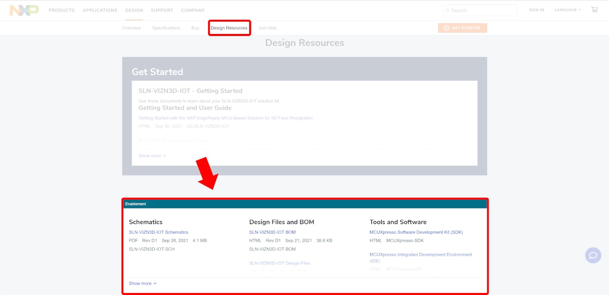
Schematics including assembly files, 3D files, ODB files, and more can be found on the main website for the SLN-VIZN3D-IOT near the top of the page.

Or under Design Resources in the Quick Reference bar to the left.
2.2 Install Your Toolchain
The MCUXpresso SDK is complimentary and includes full source code under a permissive open source license for all hardware abstraction and peripheral driver software.
Click below to download a preconfigured SDK release for the SLN-VIZN3D-IOT Development Kit.
 Get MCUXpresso SDK
To build the SDK for your preferred setup, perform the following steps:
- Select your preferred OS (Windows, Mac, Linux)
- Configure the SDK to be compatible your preferred toolchain (MCUXpresso IDE, ARMGCC)
- Use the 'Select All' button to ensure that all necessary SDK components are included in the SDK package
- Click the 'Download SDK' button

2.3 Jump Start Your Design with the MCUXpresso SDK
MCUXpresso IDE brings developers an easy-to-use Eclipse-based development environment for NXP’s microcontrollers based on Arm® Cortex®-M cores. It offers advanced editing, compiling and debugging features with the addition of MCU-specific debugging views, code trace and profiling, multicore debugging and integrated configuration tools. Its debug connections support every NXP evaluation board with a variety of open-source and commercial debug probes from Arm®, P&E Micro® and SEGGER®.
 Get MCUXpresso IDE
The MCUXpresso SDK for the SLN-VIZN3D-IOT also includes support for the command-line GCC.
2.4 Download the Android Application
For applications where a companion smartphone/tablet application might be useful, the example Smart Lock Manager APK project provides convenient source code to be used as a boilerplate/reference for developers looking to create their own companion app. The APK and its full source code can be found under the Software and Tools section on the main page for the SLN-VIZN3D-IOT.

3. Build, Run
3.1 Install the SDK
MCUXpresso SDK is a comprehensive software enablement package designed to simplify and accelerate application development with NXP's microcontrollers based on Arm® Cortex®-M cores. The MCUXpresso SDK includes production-grade software with integrated RTOS (optional), integrated stacks and middleware, reference software, and more. It is available in custom downloads based on user selections of MCU, evaluation board and optional software components.
Before building the SLN-VIZN3D-IOT SDK example projects, the target SDK needs to be imported into MCUXpresso IDE.
Using the SDK we downloaded in the previous step, import the SDK into MCUXpresso IDE by dragging the SDK zip folder into the Installed SDKs window in MCUXpresso IDE.

After dragging and dropping the SDK package, a confirmation window will pop up. Select OK to validate.

Once the package has been imported, it will be displayed in the Installed SDKs window in MCUXpresso.
3.2 Import SLN-VIZN3D-IOT Projects
The SLN-VIZN3D-IOT SDK allows you to import existing application examples as a development starting point. The following steps will show you how to import one of these example projects into MCUXpresso IDE.
From the Quickstart Panel, select Import SDK example(s).
For each SDK you have installed into MCUXpresso, a corresponding image will be shown. Select the SLN-VIZN3D-IOT image and proceed by selecting the Next button.

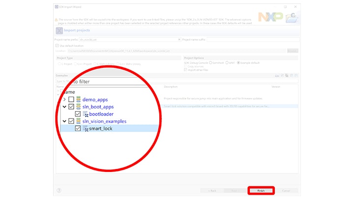
The import wizard will then display all the example applications that are available to import. For this guide, we will be focused primarily on the sln_vizn3d_iot_smart_lock application. This is the application that comes flashed by default on your SLN-VIZN3D-IOT kit.

Once the project has successfully been imported, it will be listed in the Project Explorer window, ready to be built and run.

3.3 Build a SLN-VIZN3D-IOT Project
The bootloader project is a first-stage bootloader that manages jumping into the Smart Lock application. This application can be used for any additional bootloader functionality needed for the product. The bootloader is also responsible for Mass Storage Device drag-and-drop firmware updates via USB.
The Smart Lock project is the out-of-box application used to demonstrate the capabilities of the Oasis Lite machine learning engine for secure face recognition. This application (in addition to the bootloader) is flashed on your SLN-VIZN3D-IOT kit by default.
From the Quickstart Panel, select the option Build to start the compilation and linking of the application currently highlighted in the Project Explorer panel.

Wait for MCUXpresso to finish the build process. This should take a relatively short time due to the small size of the application.

If you received a message like the one shown above, your SLN-VIZN3D-IOT project has successfully been built.
3.4 Flash and Debug SLN-VIZN3D-IOT Project
With the Smart Lock project compiled, it is now time to program its associated binary into flash.
Flashing and debugging the SLN-VIZN3D-IOT kit will require a Segger J-Link with a 9-pin Cortex-M Adapter and V7.52a or newer of the J-Link Software and Documentation Pack found on the Segger website.

To begin the process of flashing the kit, attach your J-Link debug probe into the header shown below.

Next, select the Debug option found under the Quickstart Panel in MCUXpresso to start the process of loading the binary into flash and begin debugging. Similar to the Build option, Debug will only flash and debug the project currently highlighted in the Project Explorer Panel.

Select the J-Link probe that is connected to your kit and press OK.

This will launch the flashing tool and proceed to flash the binary associated with the currently selected project.

Once flashed, the program should automatically halt at main, indicated by the first instruction in main being highlighted and pointed to.
Finally, press the Run button found in the toolbar to begin running the application. You will also find buttons to Terminate, Step In, Step Out, and Step Over in this same toolbar.

To learn more about debugging in MCUXpresso, check out the MCUXpresso User Guide.
Design Resources
Board Documents
Software
Support
Forums
Connect with other engineers and get expert advice on designing with the SLN-VIZN3D-IOT on one of our community sites.
On this page
- 1.1
Unbox
- 1.2
Power On
- 1.3
Local Registration
- 1.4
Remote Registration
- 1.5
Liveness Detection
- 1.6
Low-Power Mode
- 1.7
Connecting to Serial CLI
- 2.1
Download the Hardware Package
- 2.2
Install Your Toolchain
- 2.3
Jump Start Your Design with the MCUXpresso SDK
- 2.4
Download the Android Application