Getting Started with the MCSXSR1CS12ZVM Evaluation Board for 3-Phase BLDC/PMSM High-Current Applications
Contents of this document
-
Out of the Box
-
Get Software
-
Plug It In
-
Build and Load
Sign in to save your progress. Don't have an account? Create one.
Purchase your S12ZVM high-current BLDC/PMSM Evaluation Board
1. Out of the Box

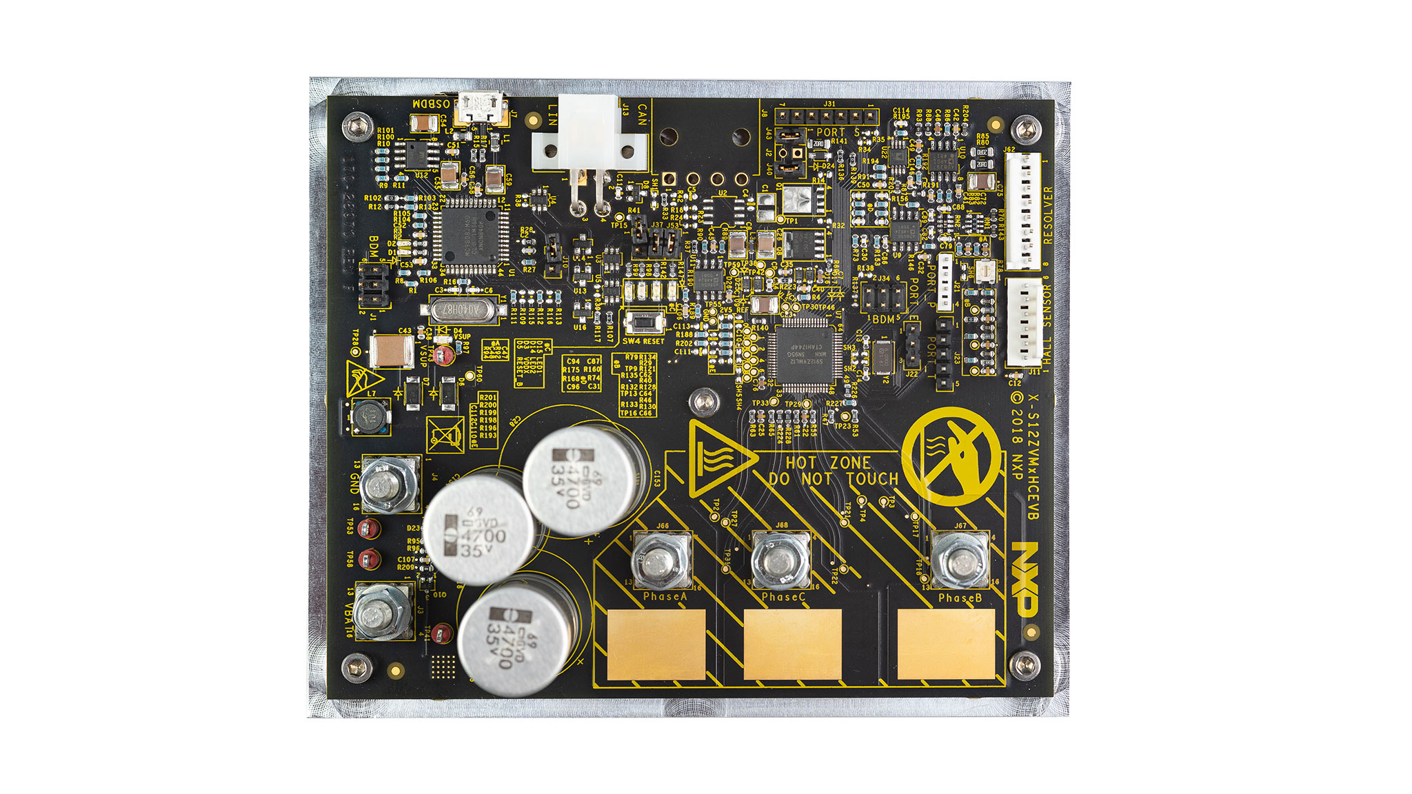
1.2 Understanding the Header/Pinout
The MCSXSR1CS12ZVM evaluation board is designed to control 3-phase AC motors up to 1 kW. Set configuration jumpers prior to application:
| MCSXSR1CS12ZVM PIN | FUNCTION | S12ZVM PIN |
|---|---|---|
J3 |
VBAT | - |
J4 |
GND | - |
J11-1 |
VCC | EVDD |
J11-2 |
GND | - |
J11-3 |
HALL_A | PT1 |
J11-4 |
HALL_B | PT2 |
J11-5 |
HALL_C | PT3 |
J11-6 |
NC | NC |
J21-1 |
GPIO | PP0 |
J21-2 |
GPIO | PP1 |
J21-3 |
GPIO | PP2 |
J21-4 |
GND | - |
J22-1 |
GPIO | PE0 |
J22-2 |
GPIO | PE1 |
J22-3 |
GND | - |
J31-1 |
GPIO | PS0 |
J31-2 |
GPIO | PS1 |
J31-3 |
GPIO | PS2 |
J31-4 |
GPIO | PS3 |
J31-5 |
GPIO | PS4 |
J31-6 |
GPIO | PS5 |
J31-7 |
GND | - |
J34-1 |
BKGD | BKGD |
J34-2 |
GND | - |
J34-3 |
NC | NC |
J34-4 |
U_RST | RST |
J34-5 |
NC | NC |
J34-6 |
+5VU | - |
J62-1 |
RES_GENP | - |
J62-2 |
RES_GENM | - |
J62-3 |
RES_SIN | - |
J62-4 |
RES_SIN_REF | - |
J62-5 |
RES_ COS | - |
J62-6 |
RES_COS_REF | - |
J62-7 |
GND | - |
J62-8 |
+5VA | - |
J66 |
PHASE_A | - |
J67 |
PHASE_B | - |
J68 |
PHASE_C | - |
2. Get Software
2.1 Download the Quick Start Package
Download the complete motor control application software for MCSXSR1CS12ZVM evaluation board.
Download the MCSXSR1CS12ZVM QSP
2.2 Get the Integrated Development Environment (IDE)
MCSXTE2BK142 performs better when using CodeWarrior® for MCUs 11.x IDE.
Download CodeWarrior for MCUs 11.x IDE
2.3 Get the Run-Time Debugging Tool
MCSXTE2BK142 performs better when using the FreeMASTER tool for run-time debugging.
You can also download and install the FreeMASTER Communication Driver (source code already included in example project).
2.4 Install an OSBDM Debug Interface Driver
Download the latest version from P&E.
Get OSBDM debug interface driver3. Plug It In
3.1 Set Up Jumpers
| JUMPER | OPTION | SETTING | DESCRIPTION |
|---|---|---|---|
J2 |
CAN VREG | Open | CAN VREG disabled (default). Short CAN VREG enabled (S12ZVMC version has to be populated). |
J10 |
OSBDM Bootloader | Open | OSBDM Bootloader update disabled (default). Short OSBDM bootloader update enable. |
J29 |
VDDX to BDM | Open | Supply of tde OSBDM from VDDX disabled (default). Short Supply of tde OSBDM from VDDX enabled. |
J37 |
LED2 Enabled | Open | User LED2 (D14) on PS5 disabled. Short user LED2 (D14) on PS5 enabled (default). |
J40 |
VDDX Ballast | Open | VSUP ballast transistor on VDDX disabled. Short VSUP ballast transistor on VDDX enabled (default). |
J43 |
VSUP to Resolver | Open | VSUP to VSUP2 for resolver disabled. Short VSUP to VSUP2 for resolver enabled (default). |
J53 |
LED1 Enabled | Open | User LED1 (D15) on PS4 disabled. Short User LED1 (D15) on PS4 enabled (default). |


4. Build and Load
Let’s take it for a test drive.
4.1 Import and Debug the Project to IDE
- To import the installed application software project in the CodeWarrior for MCUs 11.x by launch IDE by going to File → Import
- Then, select General → Existing Projects in the workspace. To choose the root directory, click Next
- Navigate to
MC_DevKits\MCSXSR1CS12ZVM\sw\... -
Then, choose your motor control driving control:
- MCSXSR1CS12ZVM_PMSM for PMSM with the field-oriented driving control
- MCSXSR1CS12ZVM_BLDC for BLDC with six-step commutation driving control

-
Click on Copy project into workspace and then click Finish.

Optional: Build Your Project
Right click on the imported project and select Clean from the context menu.

4.2 Debug for Loading Code into the MCU
To load built code into MCU, go to Run → Debug Configuration → select predefined debug configuration and click Debug button:

4.3 Communicate with the Run-Time Debugger
- Launch the FreeMASTER application
- Open a project
❮selected project❯ FreeMASTER_control\ MCSXSR1CS12ZVM_PMSM_SW_CW11.pmpby clicking File → Open Project - To enable communication, in the FreeMASTER tool bar, click Go (or press CNTRL+G)
-
Successful communication is signalized in the status bar at the very bottom as:
RS232 UART Communication;COMn; speed = 19200 - Let code run by clicking on the Resume (F8) button, and use Disconnect button for avoiding interference between CW debugger and FreeMASTER tool


4.4 Launch the Control Application
Launch the Motor Control Application Tuning (MCAT) tool, then display the application control page on the tool menu. When the power supply is connected to the board, the application is in READY state indicated by a blue LED on the board. The LED also indicates:
- READY, INIT states - slowly flashing LED
- CALIB, ALIGN states - flashing LED
- RUN state - lighting LED
- FAULT state - fast-flashing LED
4.5 Debug Your Project Using the Run-Time Debugging Tool
Run appropriate *.pmp file from your application project folder.

4.6 Establish a Connection with the MCU
- Start the application by clicking ON/OFF button on the FreeMASTER MCAT control page.

-
Set required speed by changing the Speed Required variable value manually in the variable watch window, or by clicking the speed gauge in the MCAT control tab.
4.7 Tune the Motor
Now you are ready to tune your motor control application.
- Successfully tune the control loops
- In FreeMASTER, go to the Control tab and set the required motor rpms and turn on the motor drive
- Stop the application by clicking ON/OFF button on the FreeMASTER MCAT control page


Your motor should now be running.
On this page
- 2.1
Download the Quick Start Package
- 2.2
Get the Integrated Development Environment (IDE)
- 2.3
Get the Run-Time Debugging Tool
- 2.4
Install an OSBDM Debug Interface Driver